Linear Rail Coating Apparatus and Method

a coating apparatus and linear rail technology, applied in the field of coating apparatus and method, can solve the problems of affecting the function of the device, affecting and the undesirable effects of traditional coating methods such as dip coating, so as to achieve uniform coating, reduce the effect of human factors in the coating system and increase the throughput of the devi

Inactive Publication Date: 2006-09-21
SURMODICS INC
View PDF28 Cites 41 Cited by
  • Summary
  • Abstract
  • Description
  • Claims
  • Application Information

AI Technical Summary

Benefits of technology

[0006] An apparatus of the invention includes a device rotator having at least one device mount for retaining a medical device that is to be coated. The device mount is positioned on the device rotator, the device mount being rotatable around a device axis projecting outward from the device rotator. The apparatus also includes a coating chamber capable of accommodating a device on the device mount. The coating chamber includes a coating unit and an atmospheric maintenance system that can provide a coating to the device in low humidity. The apparatus can also allow for the movement of the device rotator, the coating chamber, or both, wherein the movement can allow the device on the device mount to be inserted into and retracted from the coating chamber.
[0008] The invention provides the ability to adjust or accommodate for complex surface geometries of the device, and to provide substantially uniform coatings. The invention also eliminates human factors in the coating system, and allows for increased throughput of coated devices. Further, the invention reduces wasted coating solution and reduces operator exposure to these coating solutions.
[0009] The invention also provides an apparatus that is easy to use. The device mounts, or portions thereof, can be removable, so that an operator can easily insert and remove the devices without disassembling the apparatus. The invention also eliminates variability in coating that can result from variations in positioning of the device on the holding apparatus.

Problems solved by technology

Medical devices are becoming increasingly complex in terms of function and geometry.
Traditional coating methods, such as dip coating, are often undesirable for coating these complex geometries since coating solution may get entrapped in the device structure.
This entrapped solution may cause webbing or bridging of the coating solution and may hinder the device function.
However, current methods of spray coating have introduced operator error, and have resulted in reduced coating consistency and efficiency.

Method used


Image

  • Linear Rail Coating Apparatus and Method
  • Linear Rail Coating Apparatus and Method
  • Linear Rail Coating Apparatus and Method

Examples


example 1

EXAMPLE 1

Coating Cardiovascular Stents

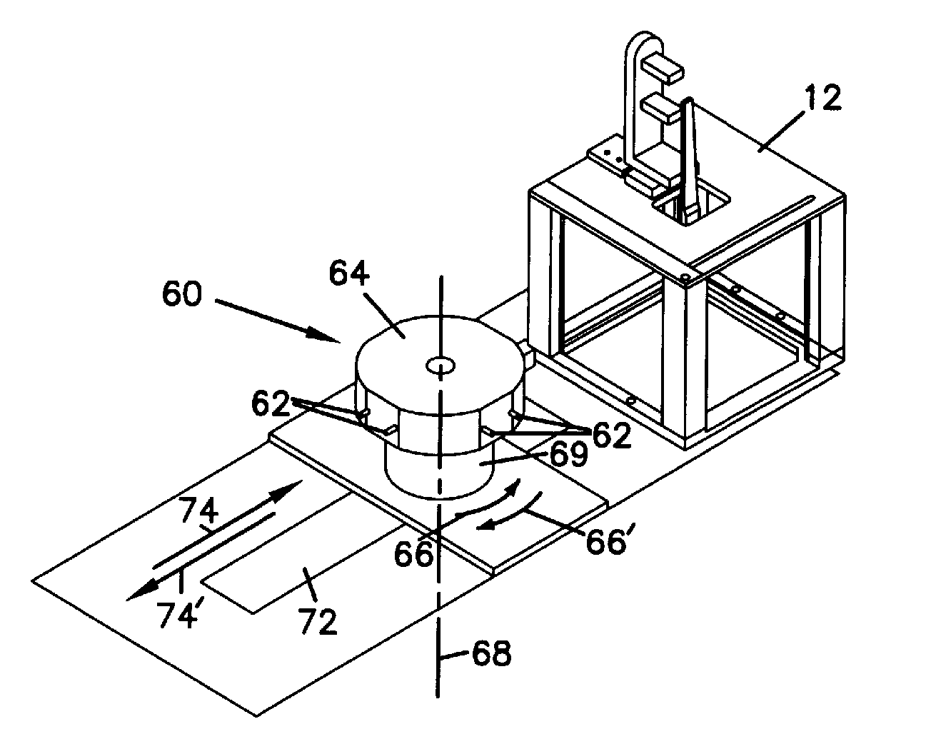
[0079] A method of the invention was performed by way of the example as follows. Cardiovascular stents of length approximately 18 mm were inserted into device grippers and a collar was slid over the juncture between the device gripper and stent. The device gripper, stent and collar were then inserted into a cavity formed in the gripper carrier. The device gripper was inserted into the gripper carrier and pushed until the device gripper seated into the chamber of the gripper carrier and was frictionally held in place. The gripper carrier was then mounted onto the shaft of the device mount of the device rotator. Nitrogen was introduced into the humidity chamber prior to introduction of the stent on the device mount to maintain approximately 10% relative humidity.

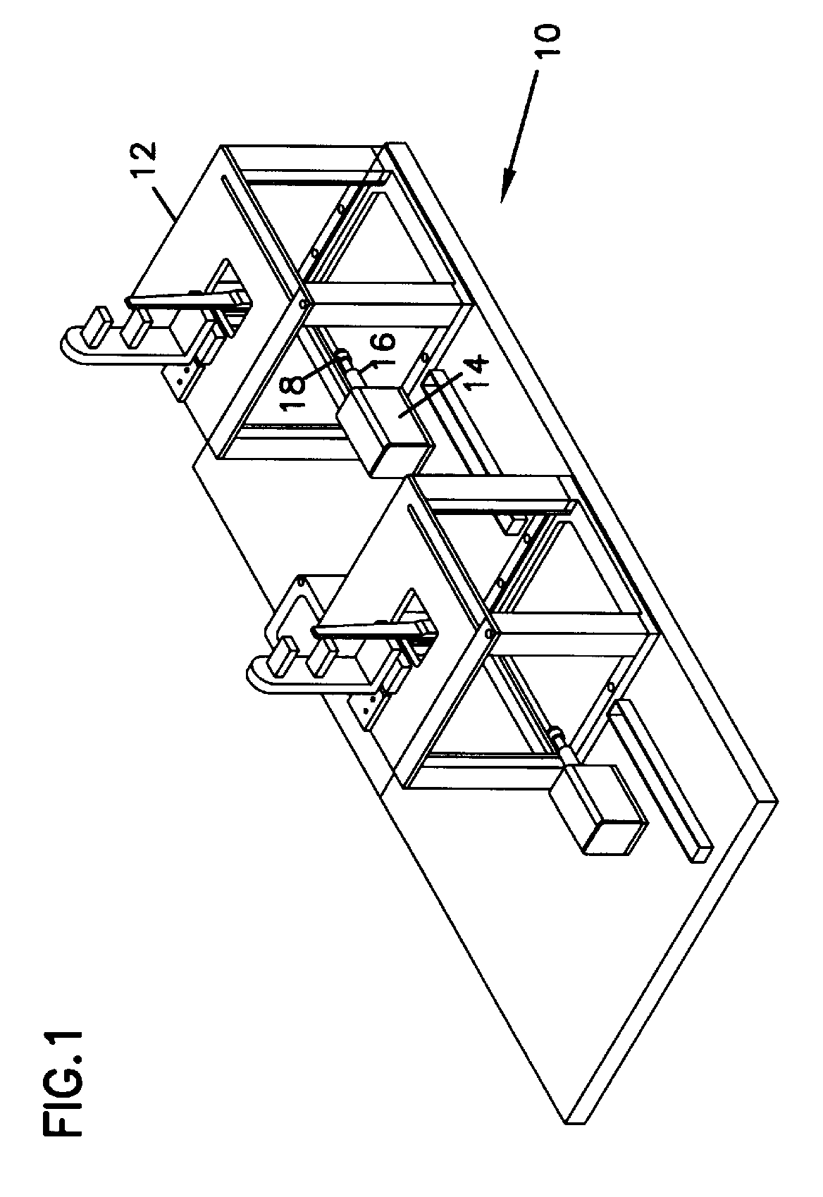
[0080] Once the stent was mounted onto the device rotator and positioned as shown in FIG. 1, a coating cycle was started. The device rotator was moved towards the coating chamber in the ...


PUM

PropertyMeasurementUnit
humidityaaaaaaaaaa
humidityaaaaaaaaaa
humidityaaaaaaaaaa

Abstract

The invention provides an apparatus for coating a device comprising a coating chamber and a device rotator having at least one device mount wherein the apparatus allows insertion and retraction of the device on the device mount into and out of the coating chamber. In another aspect, the invention provides a method of applying a substantially uniform coating on a device comprising the steps of providing an apparatus for coating a device, mounting the device onto the device mount, purging the coating chamber to reduce humidity in the coating chamber, maintaining a reduced humidity content in the coating chamber, inserting the device into the coating chamber, disposing a coating material on the device and rotating the device mounts about the device axis.

Description

REFERENCE TO CO-PENDING APPLICATIONS [0001] This application is a divisional application of U.S. patent application Ser. No. 10 / 409,434, entitled LINEAR RAIL COATING APPARATUS AND METHOD, filed Apr. 7, 2003, which is hereby incorporated by reference.FIELD OF THE INVENTION [0002] The invention relates to a coating apparatus and method for applying a coating on a device. More specifically, the invention relates to an apparatus and method for providing a coating on a device having a surface geometry, such as a medical device. The apparatus and method provide for the coating of a device in an atmosphere-regulated environment. BACKGROUND OF THE INVENTION [0003] Medical devices are becoming increasingly complex in terms of function and geometry. Traditional coating methods, such as dip coating, are often undesirable for coating these complex geometries since coating solution may get entrapped in the device structure. This entrapped solution may cause webbing or bridging of the coating sol...

Claims


Application Information

Patent Timeline
Patent Type & Authority Applications(United States)
IPC IPC(8): A61L33/00B05B13/02A61F2/06A61F2/82A61L31/10B05B13/04B05B15/12B05D1/00
CPCA61L31/10B05B13/0242B05B13/0442B05B15/1214B05D1/002B05B16/40
Inventor CHAPPA, RALPH A.PORTER, STEVEN J.
Owner SURMODICS INC
Why Eureka
Try Eureka