Honeycomb structure

Active Publication Date: 2006-09-21
IBIDEN CO LTD
View PDF51 Cites 185 Cited by
  • Summary
  • Abstract
  • Description
  • Claims
  • Application Information

AI Technical Summary

Benefits of technology

[0025] According to the honeycomb structure of embodiments of the present invention, the thickness A of the cell walls and the surface area B per unit volume of the cell walls satisfy the relation of the aforementioned exp

Problems solved by technology

Recently, it has been a problem that particulates such as soot contained in exhaust gas discharged from internal combustion engines of vehicles such as, for example, engines in buses or trucks, construction machines, etc. are harmful to environment or human bodies.
However, if the porosity of the honeycomb struct

Method used


Image

  • Honeycomb structure
  • Honeycomb structure
  • Honeycomb structure

Examples


example 1

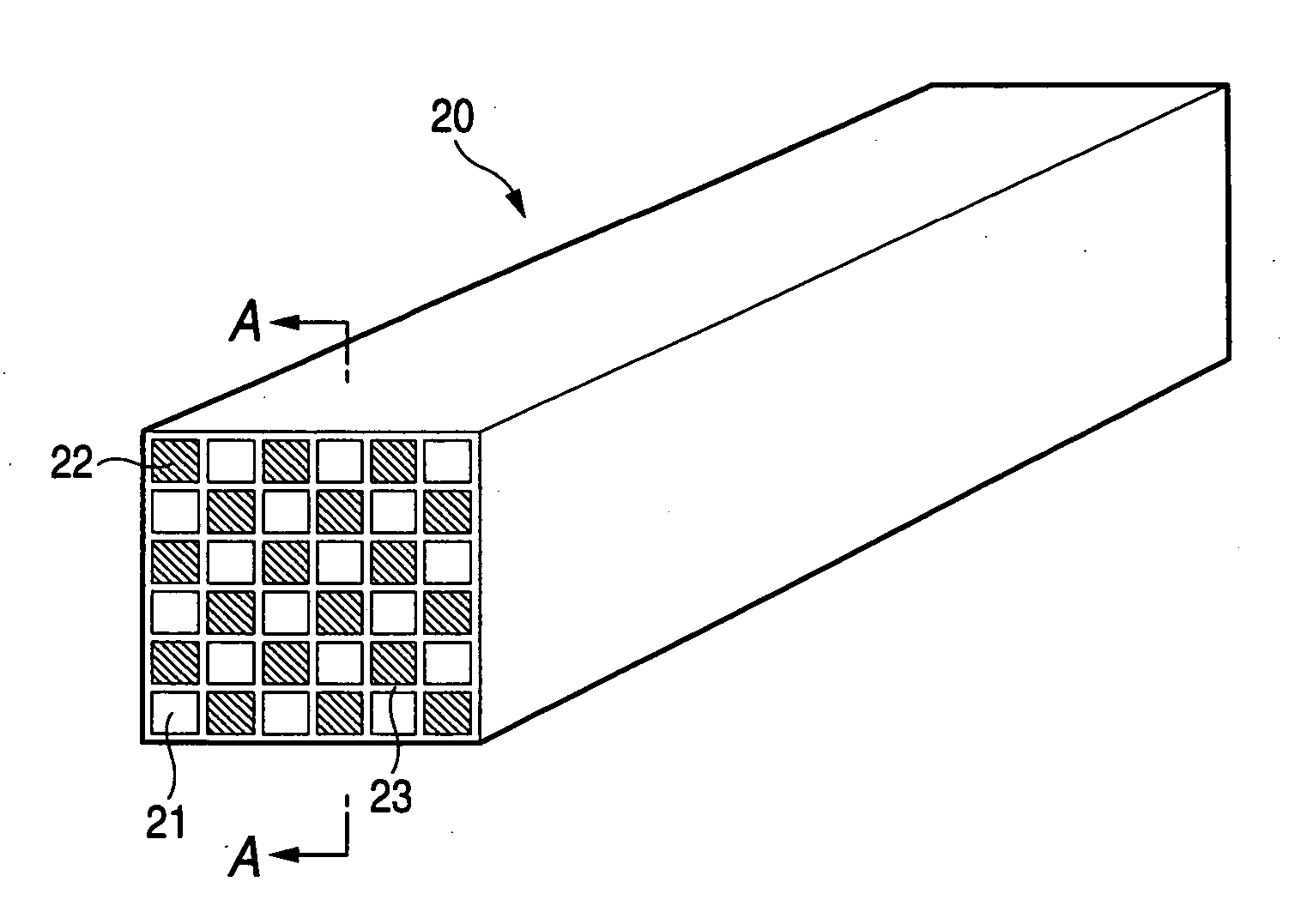
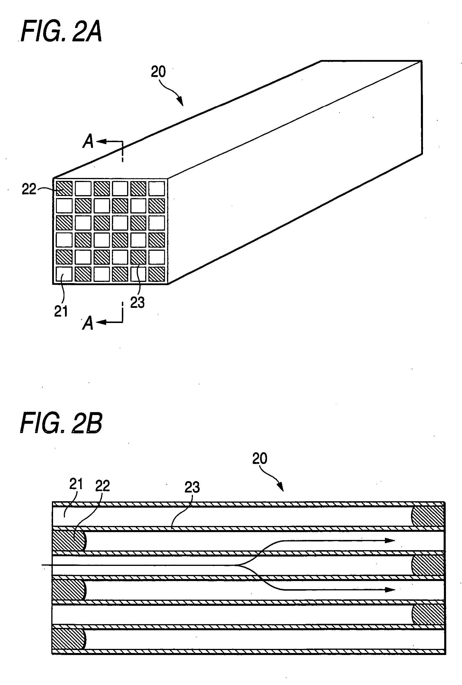
[0139] 7,000 parts by weight of coarse powder of α-silicon carbide having an average particle size of 22 μm and 3,000 parts by weight of fine powder of α-silicon carbide having an average particle size of 0.5 μm were wet-mixed. 1,100 parts by weight of organic binder (methyl cellulose), 330 parts by weight of plasticizer (Unilube made by NOF Corp.), 150 parts by weight of lubricant (glycerin) and 2,000 parts by weight of water were added to 10,000 parts by weight of the obtained mixture, and kneaded to obtain a mixture composition. After that, the mixture composition was extruded to produce a prismatic raw molded body shown in FIGS. 2A-2B.

[0140] Coarse powder subjected to oxidation treatment at 800° C. for three hours was used as the aforementioned coarse powder of α-silicon carbide.

[0141] Next, the raw molded body was dried by use of a microwave dryer or the like so as to be formed into a ceramic dried body. After that, predetermined cells were plugged with plug or plugging paste...

examples 2 and 3

[0146] Aggregate type honeycomb structures were manufactured in the same manner as in Example 1, except that the average particle size of the coarse powder of α-silicon carbide and the firing temperature of the ceramic dried body were set as shown in Table 1.

example 4

[0147] An aggregate type honeycomb structure was manufactured in the same manner as in Example 1, except that the prismatic raw molded body was produced in the following method.

[0148] That is, 5,130 parts by weight of coarse powder of α-silicon carbide having an average particle size of 22 μm and 2,200 parts by weight of fine powder of α-silicon carbide having an average particle size of 0.5 μm were wet-mixed. 490 parts by weight of acrylic particles having an average particle size of 40 μm and serving as a pore forming agent, 700 parts by weight of organic binder (methyl cellulose), 330parts by weight of plasticizer (Unilube made by NOF Corp.), 150 parts by weight of lubricant (glycerin) and a proper quantity of water were added to the obtained mixture, and kneaded to obtain a mixture composition. After that, the mixture composition was extruded to produce a prismatic raw molded body shown in FIGS. 2A-2B. Coarse powder subjected to oxidation treatment at 800° C. for three hours wa...


PUM

PropertyMeasurementUnit
Fractionaaaaaaaaaa
Pore sizeaaaaaaaaaa
Porosityaaaaaaaaaa

Abstract

A honeycomb structure including a plurality of cells arranged in parallel while being separated by cell walls, and extending in a longitudinal direction of the honeycomb structure. Each cell is sealed at one of end portions thereof. In the honeycomb structure, the relation expressed by an expression (1) is satisfied:
11/6−10/3×A≦B  (1)
    • where A (mm) designates thickness of the cell walls, and B (m2/cm3) designates a surface area per unit volume of the cell walls.

Description

CROSS-REFERENCE TO RELATED PATENT APPLICATIONS [0001] The right of priority under 35 U.S.C. §119(a) is claimed based on Japanese Patent Application No. JP 2005-075970, filed Mar. 16, 2005, the entire disclosure of which is hereby incorporated by reference. BACKGROUND OF THE INVENTION [0002] 1. Field of the Invention [0003] The present invention relates to a honeycomb structure which may serve, for example, as a filter for collecting and removing particulates etc. in exhaust gas discharged from an internal combustion engine such as, for example, a diesel engine. [0004] 2. Description of the Related Art [0005] Recently, it has been a problem that particulates such as soot contained in exhaust gas discharged from internal combustion engines of vehicles such as, for example, engines in buses or trucks, construction machines, etc. are harmful to environment or human bodies. [0006] Therefore, there have been proposed various filters using honeycomb structures made of porous ceramics for c...

Claims


Application Information

Patent Timeline
IPC IPC(8): B32B3/12
CPCB01D46/2429Y10T428/24149B01D46/2466B01D46/2474B01D2046/2433B01D2046/2496C04B38/0009C04B2111/00198C04B2111/00793F01N3/0222F01N2330/06F01N2330/30B01D46/2451Y10T428/1314Y02T10/20C04B35/565Y02T10/12B01D46/2498B01D46/24491B01D46/2484B01D46/2482B01D46/2478B01D46/2455B01D46/24492
Inventor OHNO, KAZUSHIGEOGYU, KAZUTAKE
Owner IBIDEN CO LTD
Why Eureka
Try Eureka