Magnetic recording medium and magnetic storage unit

a recording medium and magnetic storage technology, applied in the field of magnetic recording media and magnetic storage units, can solve the problems of degrading the s/n ratio, reducing the coercive force, and reducing the thermal stability of the magnetization recorded in the recording layer

Inactive Publication Date: 2006-09-21
FUJITSU LTD
View PDF12 Cites 5 Cited by
  • Summary
  • Abstract
  • Description
  • Claims
  • Application Information

AI Technical Summary

Benefits of technology

[0012] Accordingly, it is a general object of the present invention to provide a magnetic recording medium in which the above-described disadvantages are eliminated.
[0013] A more specific object of the present invention is to provide a magnetic recording medium that has an excellent S / N ratio and is employable with higher recording densities, and a magnetic storage unit and a magnetic disk unit including the same.
[0016] According to one aspect of the present invention, the recording layer of a magnetic recording medium is formed by providing a first magnetic layer and a second magnetic layer successively from the base layer side. Each of the first magnetic layer and the second magnetic layer is formed of a ferromagnetic material composed mainly of CoCrPtB. The first magnetic layer is composed so as to contain more B and less Cr than the second magnetic layer on an atomic percentage basis. By thus setting the B content, miniaturization of the crystal grains of the first magnetic layer is promoted by the action of adding B. That is, the crystal grains are reduced in size in their cross sections parallel to the substrate surface. Further, the crystal grains of the second magnetic layer grow on their corresponding crystal grains of the first magnetic layer. Accordingly, the crystal grains of the second magnetic layer are also miniaturized. As a result, the crystal grains of both the first magnetic layer and the second magnetic layer are miniaturized, so that the medium noise of the magnetic recording medium is reduced.
[0017] Further, in the first magnetic layer, by thus setting the B content, Cr and B, which are nonmagnetic elements, are diffused in the grain boundary part separating adjacent crystal grains, so that so-called segregation of Cr and B is promoted. Accordingly, the thickness of the grain boundary part increases so as to enlarge the gap between the adjacent crystal grains. This is also inherited by the second magnetic layer. Accordingly, the crystal grains of the first magnetic layer and the second magnetic layer are formed in isolation from each other, so that the magnetic or exchange interaction between the crystal grains is reduced. The medium noise is also reduced in this aspect.
[0018] On the other hand, the first magnetic layer is set to a composition such that its Cr content is less than that of the second magnetic layer. This makes it possible to increase the Co content of the crystal grains of the first magnetic layer, thereby improving the crystallinity of the crystal grains. The crystal grains are composed mainly of CoCrPtB, of which Co atoms form the skeleton of the hcp (hexagonal close packing) structure. Accordingly, the more the Co content the better the crystallinity. Further, the crystal grains of the second magnetic layer, which inherit the excellent crystallinity of the crystal grains of the first magnetic layer, have excellent crystallinity. As a result, the anisotropic magnetic field increases to increase the coercive force. Further, the saturation magnetization also increases for the same reason. Accordingly, the magnetic recording medium has characteristics suitable for high-density recording.
[0019] Accordingly, a magnetic recording medium according to the present invention is reduced in medium noise and has an excellent S / N ratio, thus being employable with higher recording densities.

Problems solved by technology

However, a mere reduction in the film thickness t of the recording layer reduces the coercive force, and increases medium noise to cause the problem of degradation of S / N ratio.
In such a recording layer, there occurs a problem in that the coercive force is reduced because the anisotropic magnetic field is reduced.
Further, the heat-resisting fluctuation characteristic of the recording layer, that is, the thermal stability of magnetization recorded in the recording layer, is degraded.

Method used


Image

  • Magnetic recording medium and magnetic storage unit
  • Magnetic recording medium and magnetic storage unit
  • Magnetic recording medium and magnetic storage unit

Examples


first embodiment

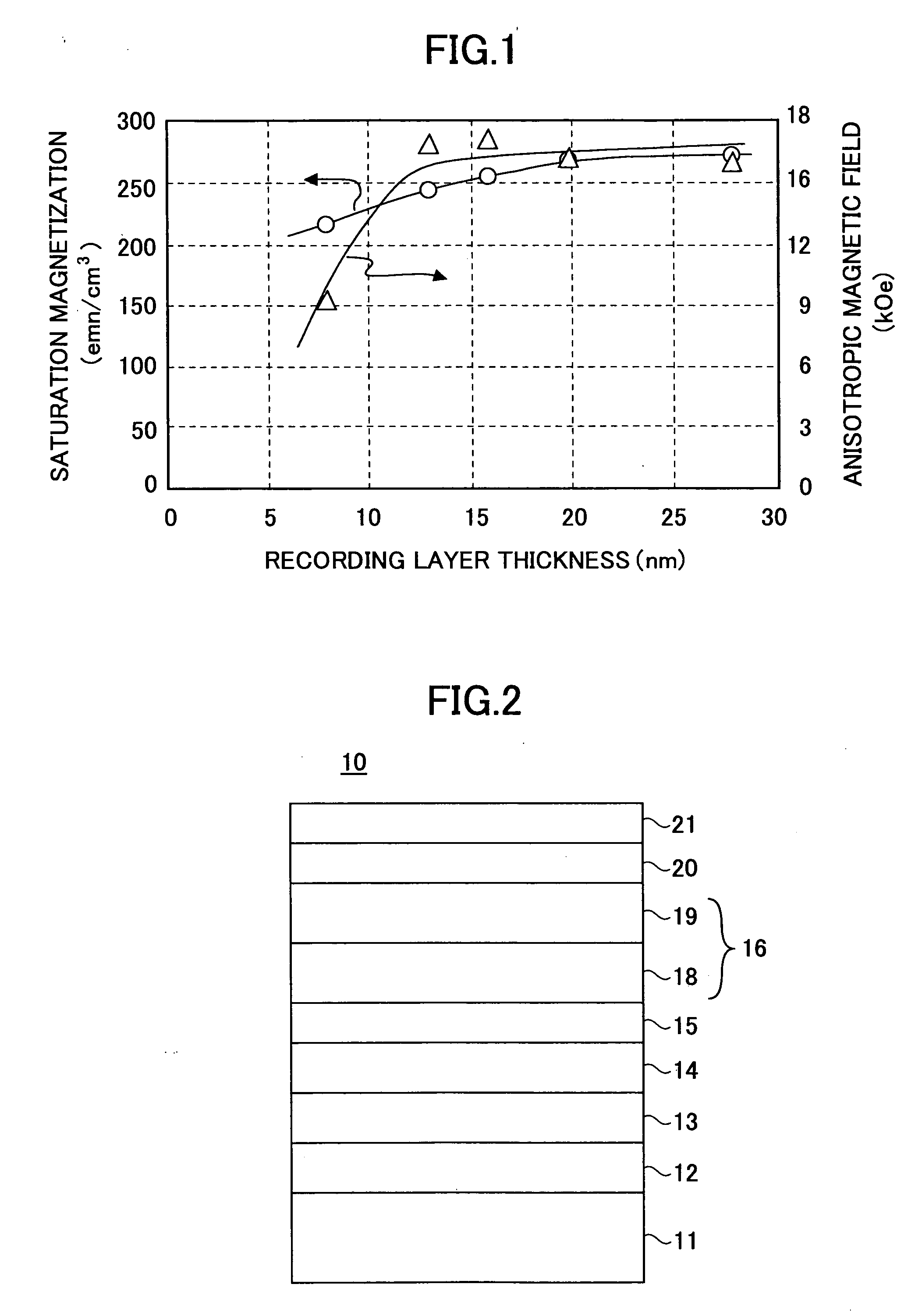
[0033]FIG. 2 is a cross-sectional view of a magnetic recording medium 10 according to a first embodiment of the present invention.

[0034] Referring to FIG. 2, the magnetic recording medium 10 includes a substrate 11, a first seed layer 12, a second seed layer 13, a base layer 14, an intermediate layer 15, a recording layer 16, a protection film 20, and a lubrication layer 21. The first seed layer 12, the second seed layer 13, the base layer 14, the intermediate layer 15, the recording layer 16, the protection film 20, and the lubrication layer 21 are formed successively on the substrate 11. The recording layer 16 has a two-layer structure of a first magnetic layer 14 and a second magnetic layer 19 provided successively from the base layer 14 side.

[0035] There is no particular limitation to the material of the substrate 11. For instance, a glass substrate, a NiP-plated aluminum alloy substrate, a silicon substrate, a plastic substrate, a ceramic substrate, and a carbon substrate may...

example

[0079] An example magnetic disk was equal in configuration to the magnetic recording medium 10 according to the first embodiment illustrated in FIG. 2. The specifics of configuration are as follows:

[0080] Glass substrate (65 nm in diameter);

[0081] First seed layer: Cr50Ti50 film (25 nm);

[0082] Second seed layer: Al50Ru50 film (25 nm);

[0083] Base layer: Cr75Mo25 film (5 nm);

[0084] Intermediate layer: Co58Cr42 film (1 nm); First magnetic layer: Co65Cr11Pt11B13 film (10 nm);

[0085] Second magnetic layer: Co60Cr18Pt11B8Cu3 film (5 nm);

[0086] Protection film: amorphous carbon film (5 nm); and

[0087] Lubrication layer: AM3001 (1.5 nm), where the parenthesized numeric values represent thickness, and the numeric values of composition are expressed by atomic %.

[0088] The example magnetic disk was prepared as follows. First, a texture extending along a circumferential direction was formed on the surface of a glass substrate. Next, the surface of the glass substrate was cleaned, and the...

second embodiment

[0101]FIG. 8 is a plan view of part of a magnetic storage unit 60 according to a second embodiment of the present invention.

[0102] Referring to FIG. 8, the magnetic storage unit 60 includes a housing 61. Inside the housing 61, a hub 62 driven by a spindle (not graphically illustrated), a magnetic recording medium 63 fixed to the hub 62 and rotated, an actuator unit 64, an arm 65 and a suspension 66 attached to the actuator unit 64 and moved in the radial directions of the magnetic recording medium 63, and a magnetic head 68 supported by the suspension 66 are provided. The magnetic head 68 is formed of a composite head of a reproduction head of an MR element (magnetoresistive element), a GMR element (giant magnetoresistive element), or a TMR element (tunnel magnetoresistive element), and an induction-type recording head. The basic configuration itself of this magnetic storage unit 60 is well known, and a detailed description thereof is omitted in this specification.

[0103] The magne...


PUM

PropertyMeasurementUnit
thicknessaaaaaaaaaa
thicknessaaaaaaaaaa
thicknessaaaaaaaaaa

Abstract

A magnetic recording medium is disclosed that includes a substrate, a base layer provided on the substrate, and a recording layer provided on the base layer. The recording layer includes a first magnetic layer and a second magnetic layer from the base layer side. Each of the first magnetic layer and the second magnetic layer includes a ferromagnetic material composed mainly of CoCrPtB. The first magnetic layer contains more B and less Cr than the second magnetic layer on an atomic percentage basis.

Description

BACKGROUND OF THE INVENTION [0001] 1. Field of the Invention [0002] The present invention relates generally to magnetic recording media and magnetic storage units, and more particularly to a magnetic recording medium with a recording layer having multiple magnetic layers and a magnetic storage unit including the same. [0003] 2. Description of the Related Art [0004] In recent years, magnetic storage units, for instance, magnetic disk units, have been used for a wide variety of purposes as storage units for digitized video and music. In particular, the magnetic disk unit has been used for home video recording, and with its characteristics of high-speed access, small size, and large capacity, has been taking the place of the conventional home video apparatus, so that its market scale has increased remarkably. Video has a large amount of information in particular, which requires the magnetic disk unit to be increased in capacity. Therefore, for a further increase in recording density, w...

Claims


Application Information

Patent Timeline
Patent Type & Authority Applications(United States)
IPC IPC(8): G11B5/66
CPCG11B5/656G11B5/66G11B5/732G11B5/7325G11B5/7379G11B5/7368G11B5/7377G11B5/737G11B5/7373G11B5/672
Inventor GOUKE, TAKASHI
Owner FUJITSU LTD
Why Eureka
Try Eureka