Abrasive disc

a technology of diamond abrasives and discs, which is applied in the field of discs, can solve the problems of difficult to use diamond abrasives to abrade the curved surface, generating centrifugal force and mechanical vibration and shocks, and injuring the operator or damage the obj

Inactive Publication Date: 2006-09-21
GOEI
View PDF20 Cites 33 Cited by
  • Summary
  • Abstract
  • Description
  • Claims
  • Application Information

AI Technical Summary

Benefits of technology

[0020] The each abrasive chip is independently contacted in compliance to the surface of the object to be abraded.

Problems solved by technology

There is a problem that the centrifugal force and mechanical vibration and shocks are generated to the abrasive chips to be ablated from the disc substrate when the disc substrate is rotated in a high speed to abrade the objects to be abraded.
When the abrasive chips are stripped off from the abrasive disc, then it is scattered and may injure the operator or damage the object.
Therefore it is difficult to use the diamond abrasive disc to abrade the curved surface.
Since the diamond abrasive disc does not elastically conform to meet the curved surface of the objects due to the hardness of the disc substrate, the uniformly tight contact between the diamond abrasive disc and the object is hardly obtained and therefore it is not possible to obtain the smoothened surface of such curved surface in the abrasion.
Due to the hardness

Method used


Image

  • Abrasive disc
  • Abrasive disc
  • Abrasive disc

Examples


Embodiment Construction

[0045] In reference to the attached drawings, the present invention is explained in details as follows.

[0046] The definition of “upper” is that the upper direction when the disc substrate is placed such a way that the fixing hole is set in the horizontal plane the surface of the abrasive chips are facing to the upward. The definition of “lower” is that the lower direction when the disc substrate is placed such a way that the fixing hole is set in the horizontal plane the tail surface of the abrasive chips are directing to the downward. The upper direction and the lower direction direct various directions in accordance to the abrasive disc setting direction and orientation.

[0047] It should be notified that the same numeric figures and letters are used for the elements and components in the drawings for the purpose that the repeated explanations for the elements and the components are avoided.

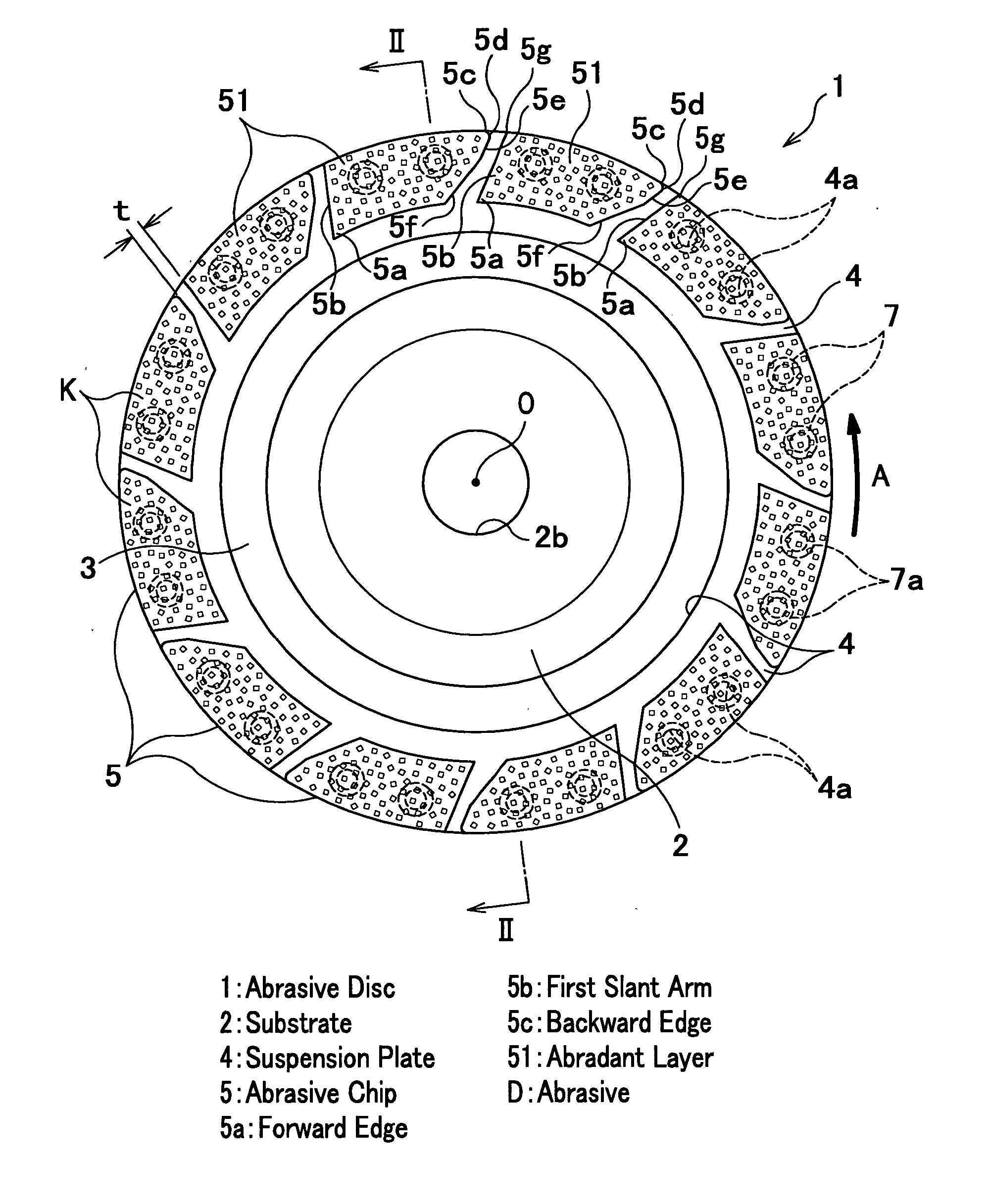
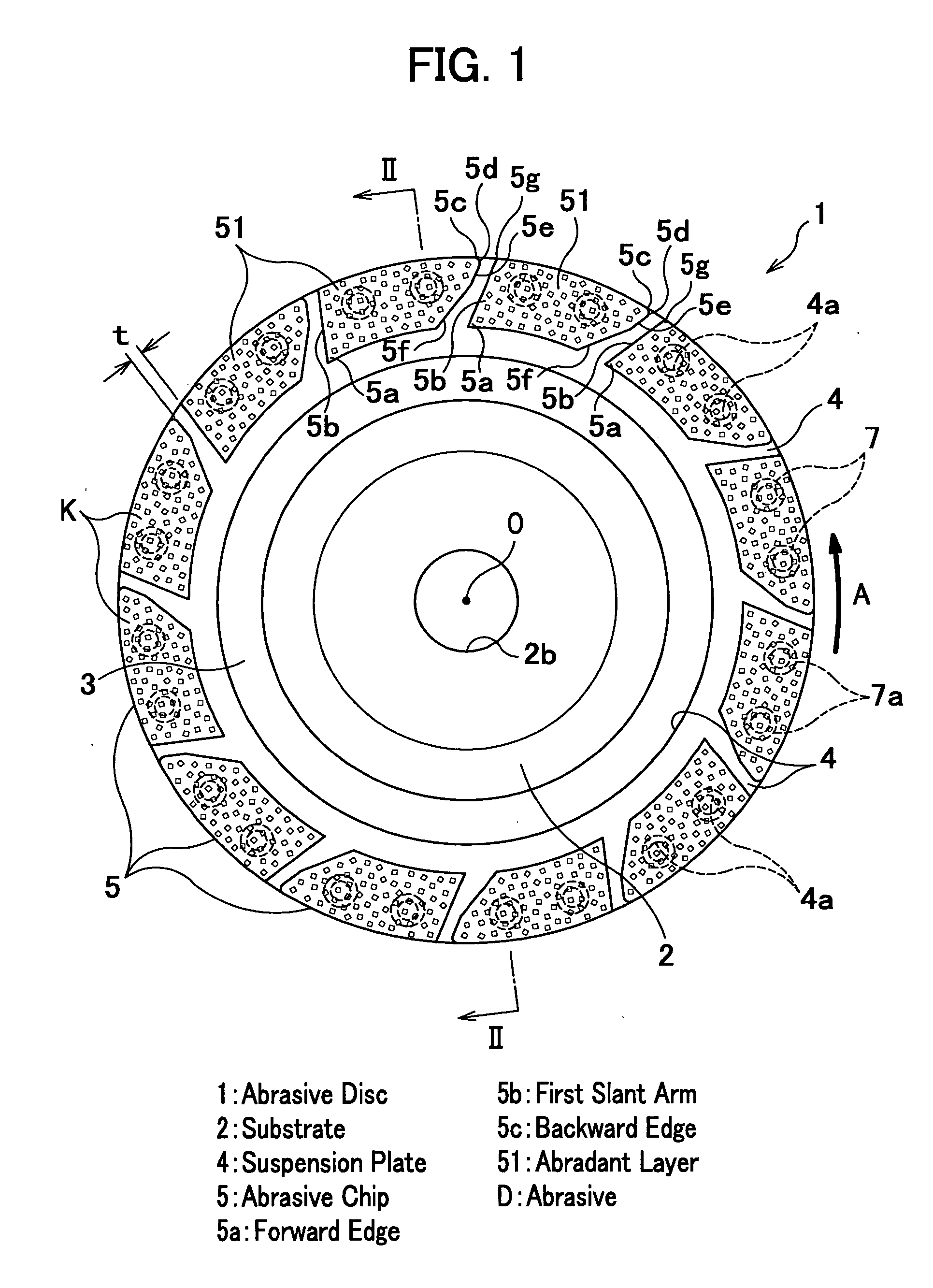
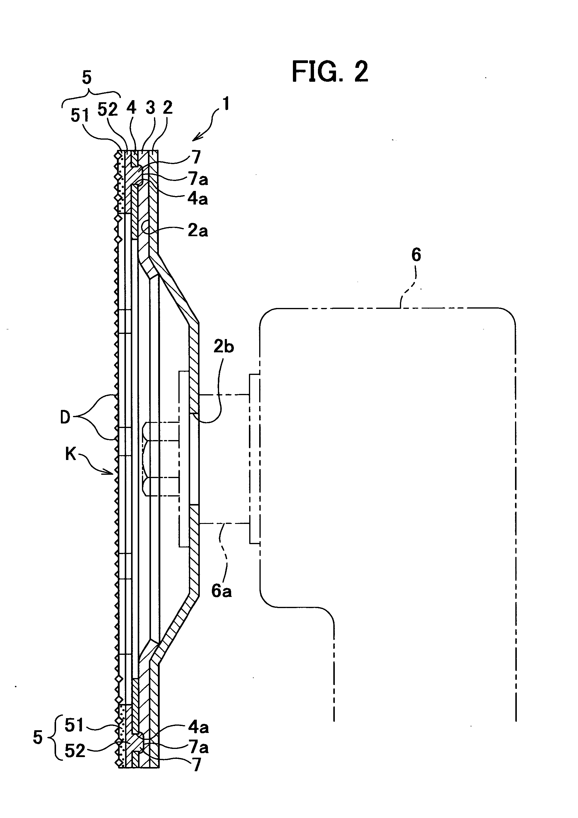
[0048]FIG. 1 is a schematic that shows a plan view of an abrasive disc, FIG. 2 is a schema...


PUM


Abstract

An abrasive disc which has plural abrasive chips having an abrasive layer on a metal piece and being arranged in a peripheral portion of a disc substrate with a predetermined space comprises a suspension plate placed between the disc substrate and abrasive chips and an elastic sheet placed between the disc substrate and the suspension plate, wherein the disc substrate consists of a plastic resin including fiber, the abrasive chips have stakes therein and the suspension plate has through-holes to which the stakes are deformed therein. Each of the abrasive chips has abrasive surfaces including a top abrasive surface and peripheral surfaces and the outer peripheral portion and the inner peripheral portion are declined to the top surface. The abrasive discs have a combination of different abrasive chips fabricated by different bonding metals for the fabrication of the abrasive chips.

Description

FIELD OF INVENTION [0001] The present invention relates to a disc which has a capability to ablate the coating layer coated onto the surface of the hard materials, remove rusts or stains covering the metal surfaces or abrade metal surfaces, metal rods, structured materials made of concrete, etc. [0002] It has been well known that a diamond abrasive disc has been used for abrasive disc for abrasion tools. A metal-bonded diamond abrasive disc that has diamond abrasive bound by metal powder, both of which are sintered onto the disc surface and a diamond deposition abrasive disc manufactured by electric deposition bonding have been used for the diamond abrasive discs. [0003] Many of the conventional diamond abrasive discs are formed with a planer metal disc substrate on which abrasive layers are directly made (as described, for instance, in the reference 1). [0004] Since grooves are made on the abrasive discs, the abrasive layers which have function to abrade objects, called abrasive ch...

Claims


Application Information

Patent Timeline
IPC IPC(8): B23F21/03B24B33/00
CPCB24D7/06
Inventor KODANI, NORIOMINAGAYA, AKIHIKOKAWASAKI, KATSUHIRO
Owner GOEI
Why Eureka
Try Eureka