Cermanic filter for exhaust gas emission control

a technology of carbon fiber filters and exhaust gas, which is applied in the direction of filtration separation, auxillary pretreatment, separation processes, etc., can solve the problems of cracking when the filter exceeds the strength limit, and achieve the effect of superior strength

Active Publication Date: 2006-09-28
IBIDEN CO LTD
View PDF28 Cites 68 Cited by
  • Summary
  • Abstract
  • Description
  • Claims
  • Application Information

AI Technical Summary

Benefits of technology

[0012] It is an object of the present invention to provide a ceramic filter assembly having superior strength. It is a further a

Problems solved by technology

The inventor has confirmed that this temperature difference prevents uniform reproductio

Method used


Image

  • Cermanic filter for exhaust gas emission control
  • Cermanic filter for exhaust gas emission control
  • Cermanic filter for exhaust gas emission control

Examples


examples 2-1 to 2-4

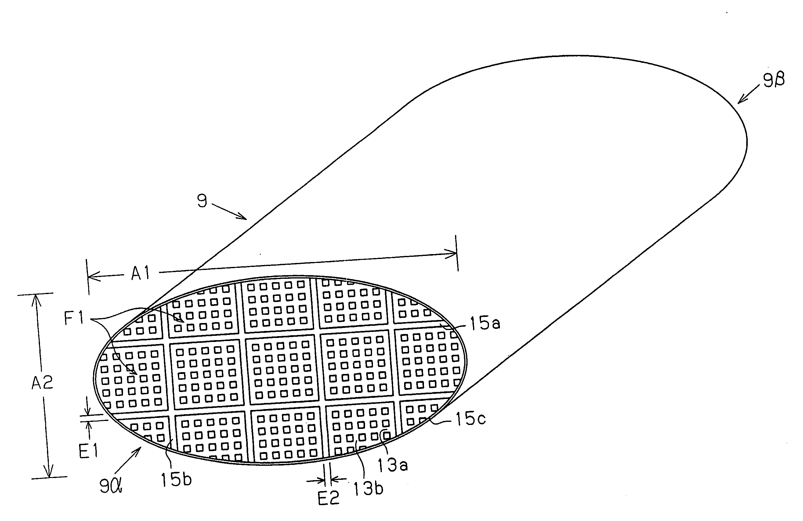
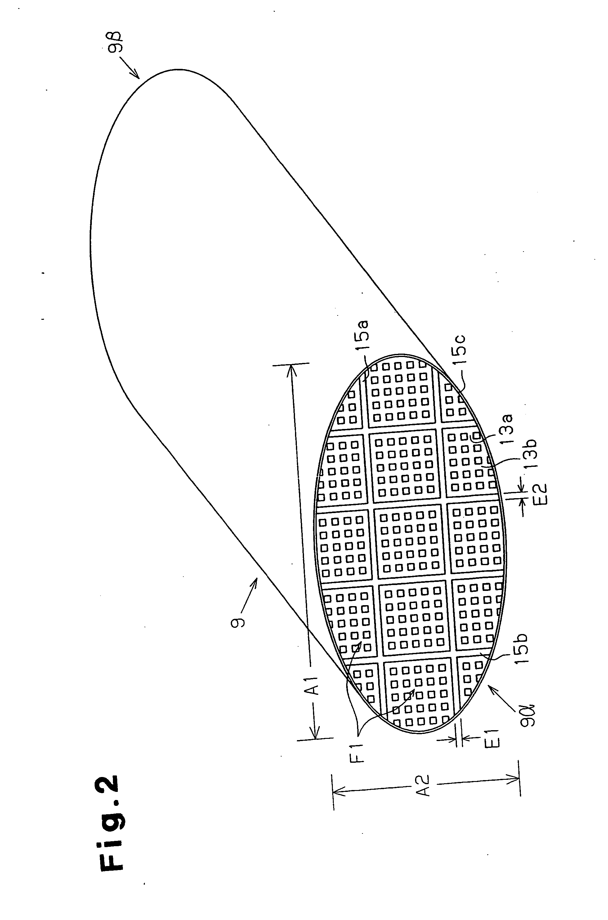
[0126] In examples 2-1 to 2-4, the assembly 9 was manufactured basically in the same manner as in comparative examples 1-3. In example 2-1, in the cells 12 of each honeycomb filter F1, C1 was set to 1.7 mm and C2 was set to 1.5 mm. Therefore, C1 / C2=1.13. Five honeycomb filters F1 were arranged parallel to the long side of the cell 12, and three honeycomb filters F1 were arranged perpendicular to the long side of the cells 12 to assemble an assembly of fifteen honeycomb filters F1. The outer shape cutting process was performed to manufacture an assembly 9d (160 mm×80 mm×150 mm) having a substantially elliptical cross section, as shown in FIG. 7(a). As shown in table 8, examples 2-2 to 2-4 differ from example 2-1 only in the dimensions of the cells 12.

examples 2-5 to 2-8

, Comparative Examples 2-5 to 2-8

[0130] In the same manner, the maximum temperature difference ΔT (° C.) and the occurrence of cracks in the silicon carbide-metal silicon filter were studied.

[0131] More specifically, in examples 2-5 to 2-8, the filters of test examples 4.1 to 4.4 (table 4) were used in a state assembled as shown in the assembly of FIG. 7(a). In comparative example 2-5, the filters of the test reference example 4.1 were used in a state assembled as shown in FIG. 7(b). In comparative examples 2-6, 2-7, the filters of test examples 4.1 and 4.2, were used in a state assembled as shown in the assembly of FIG. 7(c). In comparative example 2-8, the filters of test comparative example 4.1 were used in a state assembled as shown in the assembly of FIG. 7(a).

[0132] The maximum temperature difference ΔT (° C.) of examples 2-5 to 2-8 was 110° C. or less, whereas the maximum temperature difference ΔT (° C.) of comparative examples 2-5 to 2-8 was 110° C. or greater, and cracks ...

examples 3-1 to 3-4

[0134] In examples 3-1 to 3-4, the assembly 9 was manufactured basically in the same manner as in comparative example 1-3. However, in example 3-1, the dimension D1 of the cell wall 13 of each honeycomb filter F1 was changed to 0.4 mm, and D2 was changed to 0.35 mm. Therefore, D1 / D2=1.14. Five honeycomb filters F1 were arranged parallel to D1 and three honeycomb filters F1 were arranged perpendicular to D1 to form an assembly of fifteen honeycomb filters F1. The outer shape cutting process was performed to manufacture an assembly 9g (160 mm×80 mm×150 mm) having a substantially elliptical cross section, as shown in FIG. 8(a). In the same manner, the assembly of examples 3-2 to 3-4 were manufactured.

Comparative Examples 3-4l to 3-4

[0135] The assembly was also manufactured basically in the same way as in example 3-1 in comparative examples 3-1 to 3-4. However, in comparative example 3-1, the dimension D1 was changed to 1.5 mm, and D2 was changed to 1.5 mm. Therefore, ratio D1 / D2=1. A...


PUM

PropertyMeasurementUnit
Thicknessaaaaaaaaaa
Thicknessaaaaaaaaaa
Temperatureaaaaaaaaaa

Abstract

A ceramic filter assembly (9) that resists cracking. The ceramic filter assembly is formed by integrating a plurality of columnar honeycomb filters (F1) made of a porous ceramic sintered material with a ceramic sealing material layer and formed to have a substantially elliptical cross sectional shape. The honeycomb filters includes square columnar honeycomb filters in which the ratio between the lengths of their long sides and short sides is between 1.1 and 3.0. The honeycomb filters are arranged so that the long sides and the short sides are respectively parallel to the major axis and the minor axis of the assembly.

Description

RELATED APPLICATION [0001] This application claims priority from Japanese Patent Application No. 2002-72847 filed on Mar. 15, 2002. TECHNICAL FIELD [0002] The present invention relates to ceramic filters for exhaust gas emission control, and more particularly, to a ceramic filter assembly in which a plurality of filters made of a ceramic sintered material are integrated, a canning body, and a columnar honeycomb filter that may be used when manufacturing the same. PRIOR ART [0003] The number of automobiles is dramatically increasing, and in proportion thereto, the amount of exhaust gas exhausted from internal combustion engines of automobile is also rapidly increasing. Various substances contained in the exhaust gas, especially from diesel engines cause pollution, and thus presently, are seriously affecting the world environment. Reports have been recently made on study results that fine particles (diesel particulate) in the exhaust gas may sometimes cause allergic symptoms or reduce...

Claims


Application Information

Patent Timeline
IPC IPC(8): B01D46/00B01D39/20B01D46/24F01N3/02F01N3/021F01N3/022F01N3/035F01N13/04
CPCB01D39/2068B01D46/2422B01D46/2444B01D46/2448B01D46/2451B01D46/2455B01D46/2459B01D46/2462B01D46/2466B01D46/247B01D46/2474B01D2046/2481B01D2046/2492B01D2046/2496F01N3/0211F01N3/0222F01N3/035F01N2260/10F01N2330/06F01N2330/34F01N2330/48F01N2340/00F01N2450/28F01N3/2853Y10S55/30Y10S55/10F01N13/017B01D46/249B01D46/2486B01D46/2498B01D46/2478B01D46/2476B01D46/2482B01D46/24494
Inventor TAOKA, NORIYUKIYOSHIDA, YUTAKA
Owner IBIDEN CO LTD
Why Eureka
Try Eureka