Production of submicron diameter fibers by two-fluid electrospinning process

a two-fluid electrospinning and fiber technology, applied in separation processes, gravity filters, filtration separation, etc., can solve problems such as difficult processing

Inactive Publication Date: 2006-09-28
MASSACHUSETTS INST OF TECH
View PDF0 Cites 84 Cited by
  • Summary
  • Abstract
  • Description
  • Claims
  • Application Information

AI Technical Summary

Benefits of technology

[0020] Either the core or shell fluids can be doped with additives. For example, the core fluid can carry a drug while the shell served as a thin barrier for controlled, long-term release. Alternatively, the shell fluid can carry surface active agents such as biocides, chemical agent neutralizers, or coagulants, while the core provides structural support and longevity.

Problems solved by technology

The fluid used to form the core fiber can be electrospinnable, but preferably it is either not electrospinnable at all or is very hard to process using conventional single fluid spinning methods.

Method used


Image

  • Production of submicron diameter fibers by two-fluid electrospinning process
  • Production of submicron diameter fibers by two-fluid electrospinning process
  • Production of submicron diameter fibers by two-fluid electrospinning process

Examples


example 1

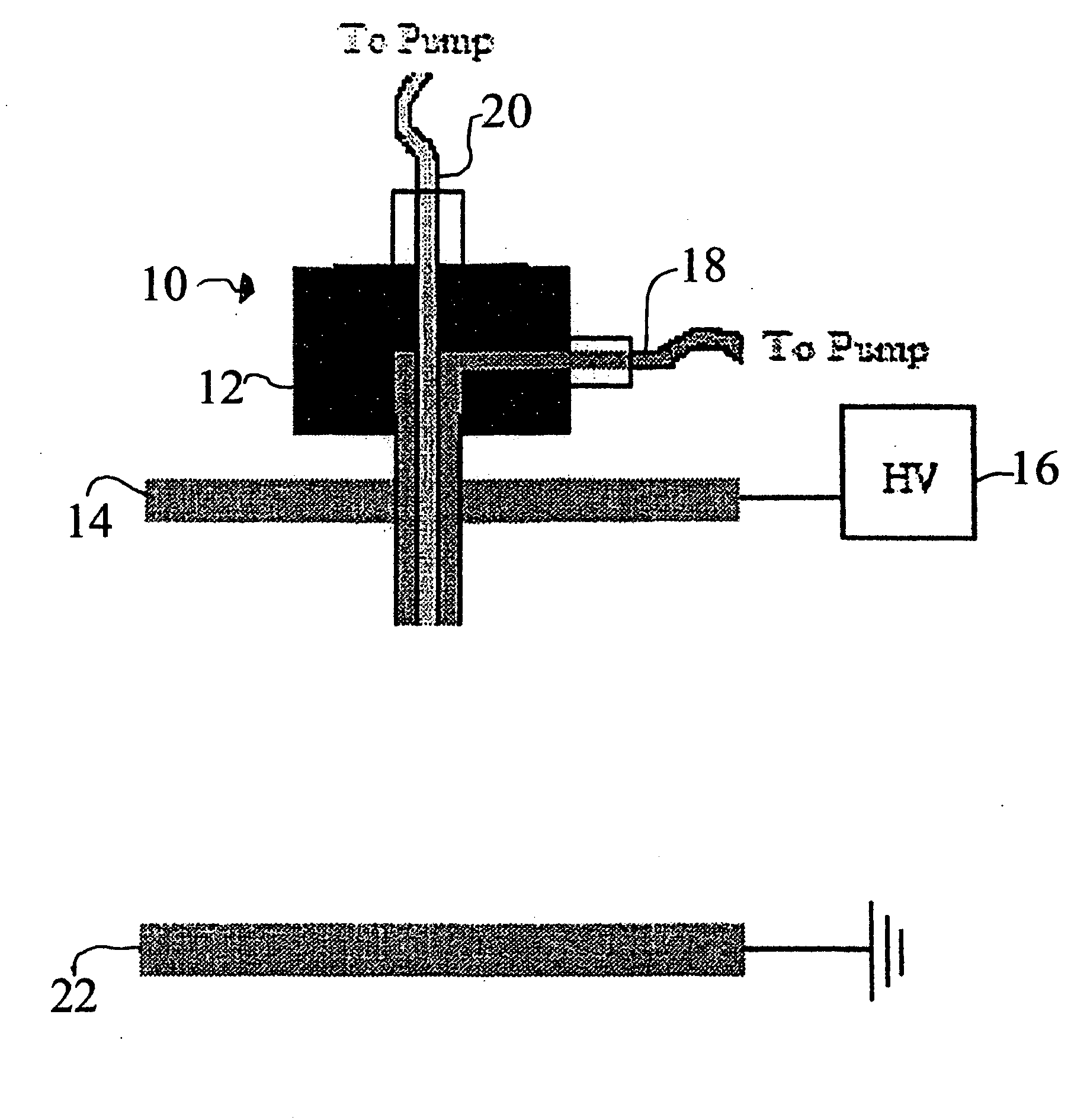
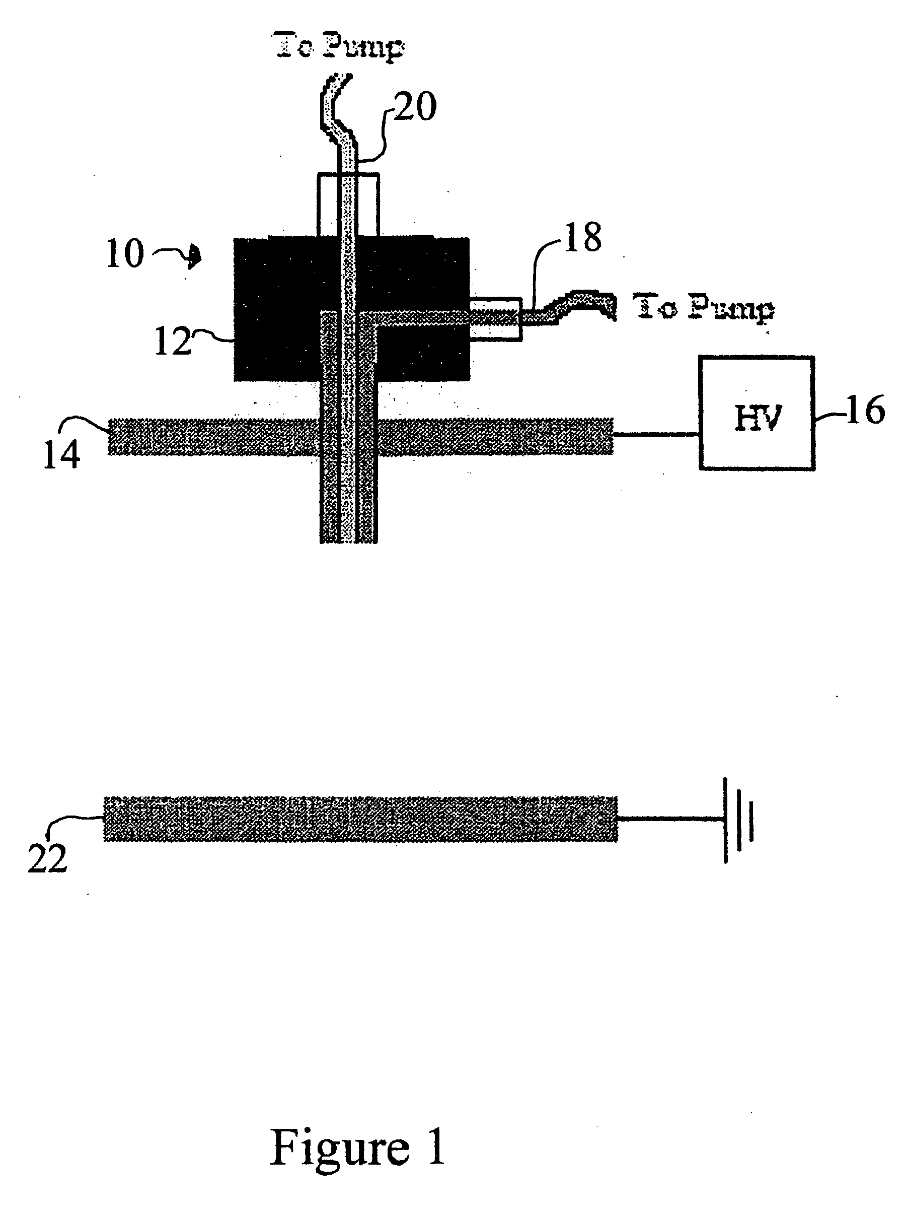
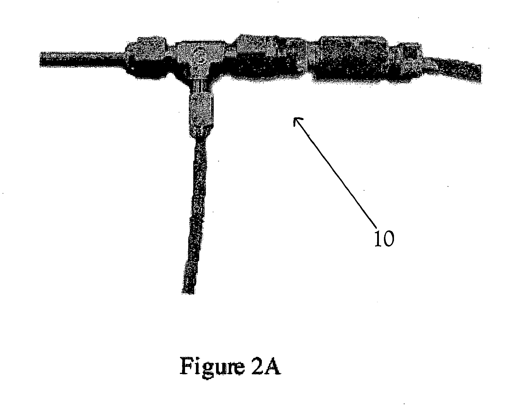
[0035] A two-fluid electrospinneret as shown in FIG. 2 was used to prepare a nanofiber having a core of polyacrylonitrile (PAN), which is of particular interest as a precursor to carbon nanofibers. PAN (MW 150,000) was dissolved in N,N-dimethylformamide (DMF) to form an 8 wt % solution. The fluid used for the outer shell layer was 20 wt % polyacrylonitrile-co-polystyrene (PAN-co-PS) (MW 165,000) dissolved in N,N-dimethylformamide.

[0036] The two fluids were processed through the electrospinneret at a voltage of 26 kV and using a disk separation of 40 cm. The PAN had a flow rate of 0.008 ml / min. The PAN-co-PS had a flow rate of 0.07 ml / min.

[0037]FIG. 3A is an SEM image of the resultant core-shell fiber produced. FIGS. 3B and 3C are axial and lateral TEM views of the fiber.

[0038] Although the formation of PAN fibers with diameters of 50 nm have been reported in the literature, the overall size distribution in that case was bimodal, with average diameters around 100 nm and 200 nm. Th...

example 2

[0039] The procedure of Example 1 was repeated to produce additional PAN fibers at varying polymer concentrations. The concentrations and electrospinning conditions used were:

Systems123Voltage26 kV28 kV30 kVDisk40 cm40 cm35 cmSeparationCore-fluid8% wt5% wt3% wtPolyacrylonitrilePolyacrylonitrilePolyacrylonitrile(PAN)(PAN)(PAN)Mw 150,000Mw 150,000Mw 150,000in N,N-dimethyl-in N,N-dimethyl-in N,N-dimethyl-formamideformamideformamide(DMF)(DMF)(DMF)Flow rate0.008 ml / min0.008 ml / min0.002 ml / minShell-fluid20% wt25% wt28% wtPolyacrylonitrile-Polyacrylonitrile-Polyacrylonitrile-co-Polystyreneco-Polystyreneco-Polystyrene(PAN-co-PS)(PAN-co-PS)(PAN-co-PS)25% wt25% wt25% wtacrylonitrileacrylonitrileacrylonitrileMw 165,000Mw 165,000Mw 165,000in DMFin DMFin DMFFlow rate0.07 ml / min0.07 ml / min0.04 ml / min

[0040]FIG. 5A is the SEM image of an 8 wt % polyacrylonitrile (PAN) core fiber before removal of its polyacrylonitrile-co-polystyrene (PAN-co-PS) shell. The average fiber diameter was about 500 nm. ...

example 3

[0046] Nanofiber polyaniline (PAni) is of an interest for the formation of conducting nanowires, but is difficult to process in part due to low molecular weight and limited solubility in electrospinnable solutions.

[0047] Thus the procedure of Example 1 was repeated with a PAni / PVA—polyanilinesulfonic acid / polyvinyl alcohol—core / shell system. The electrospinning conditions and the fluids used were:

System4Voltage20 kVDisk25 cmSeparationCore-fluid5% wt Poly(anilinesulfonic acid)(PAni) in waterFlow rate0.005 ml / minShell-fluid8% wt Poly(vinyl alcohol) (PVA)Mw 146,000-86,000; in waterFlow rate0.01 ml / min

[0048] Examination of the resulting fibers showed that the PAni / PVA fibers had an average diameter of 310 nm. A lateral TEM image showed that the PAni core had a diameter of 120 nm. About a third of the fibers did not exhibit the core / shell structure. PAni is significantly more conductive than PVA, and it is believed that it has a higher volume charge density than PVA solution and thus ...


PUM

PropertyMeasurementUnit
core diameteraaaaaaaaaa
diameteraaaaaaaaaa
core diameteraaaaaaaaaa

Abstract

Electrospinning of materials that are difficult or impossible to process into nanofibers by conventional fiber-forming techniques or by electrospinning are prepared by an electrospinning procedure which uses an electrospinnable outer “shell” fluid around an inner “core” fluid, which may or may not be electrospinnable, to form nanofibers of the inner core fluid having a core/shell morphology. The resulting shell around the nanofiber can remain in place or be removed during post-processing with the core of the fiber remaining intact. The dual-fluid electrospinning process can produce core fibers having diameters less than 100 nm, insulated nanowires, as well as tough, bio-compatible silk fibers. Alternatively, the core can be removed leaving a hollow fiber of the shell fluid.

Description

U.S. GOVERNMENT INTERESTS [0001] This invention was made with U.S. government support under a co-operative agreement awarded by the U.S. Army. The U.S. government may have certain rights to the invention.BACKGROUND OF THE INVENTION [0002] Electrostatic fiber formation, or “electrospinning” is a process that employs electrostatic forces to produce fibers with diameters ranging from microns down to tens of nanometers—two to three orders of magnitude smaller than those produced by conventional fiber spinning methods. While electrospinning of fibers first occurred in the 1930's (U.S. Pat. No. 2,077,373) (1934), the process has only recently attracted greater attention due to its simplicity in making nanofibers from both synthetic and natural polymers. [0003] Electrospinning itself is quite general. Despite the fact that over 30 different polymers have been electrospun in batch or continuous mode to produce fibers with diameters below 1 micron, there are still many fluids that cannot be ...

Claims


Application Information

Patent Timeline
Patent Type & Authority Applications(United States)
IPC IPC(8): B01D24/00B01D39/00
CPCD01D5/0007D01F8/02D01F8/08D01F8/10D01F8/16
Inventor RUTLEDGE, GREGORY C.YU, JIAN H.FRIDRIKH, SERGEY V.
Owner MASSACHUSETTS INST OF TECH
Why Eureka
Try Eureka