Etching method and apparatus

a technology of etching method and etching method, which is applied in the direction of fluid pressure measurement, instruments, vacuum gauges, etc., can solve the problems of not disclosed a consistent and reliable method, large amount of effort and time required to determine the flow rate ratio, etc., and achieves the effect of improving the flow rate, improving the processing accuracy after etching, and high in-surface uniformity of etching characteristics

Active Publication Date: 2006-09-28
TOKYO ELECTRON LTD
View PDF14 Cites 17 Cited by
  • Summary
  • Abstract
  • Description
  • Claims
  • Application Information

AI Technical Summary

Benefits of technology

[0010] The present invention has been conceived from the above problems; and it is, therefore, an object of the present invention to provide a technology capable of improving in-surface uniformity when an etching is performed on a substrate by using gas containing carbon and halogen.
[0021] As described above, in accordance with the present invention, when etching is performed on an etching target film formed on a substrate by using a processing gas including a gas containing carbon and halogen, a supply amount of the gas containing carbon and halogen is controlled, according to the carbon number of the gas containing carbon and halogen, in such a manner that a greater flow rate is supplied to the central portion of the gas supply surface than to the peripheral portion and vice versa. Therefore, high in-surface uniformity of etching characteristics such as an etching rate, processing accuracy after etching can be achieved.

Problems solved by technology

However, due to lack of a consistent and reliable method for determining a flow rate ratio of gases supplied to the central and the periphery part for respective CF-based gases, the flow rate ratio is determined through many trials and errors to perform an etching process with a high in-surface uniformity.
Thus, a lot of efforts and time are necessary to determine the flow rate ratio.
Even in the aforementioned patent document, however, there is not disclosed a consistent and reliable method for determining a flow rate ratio of gases supplied to the central and the periphery part of the wafer W when an etching is performed by using the CF-based gas.

Method used


Image

  • Etching method and apparatus
  • Etching method and apparatus
  • Etching method and apparatus

Examples


embodiment 1

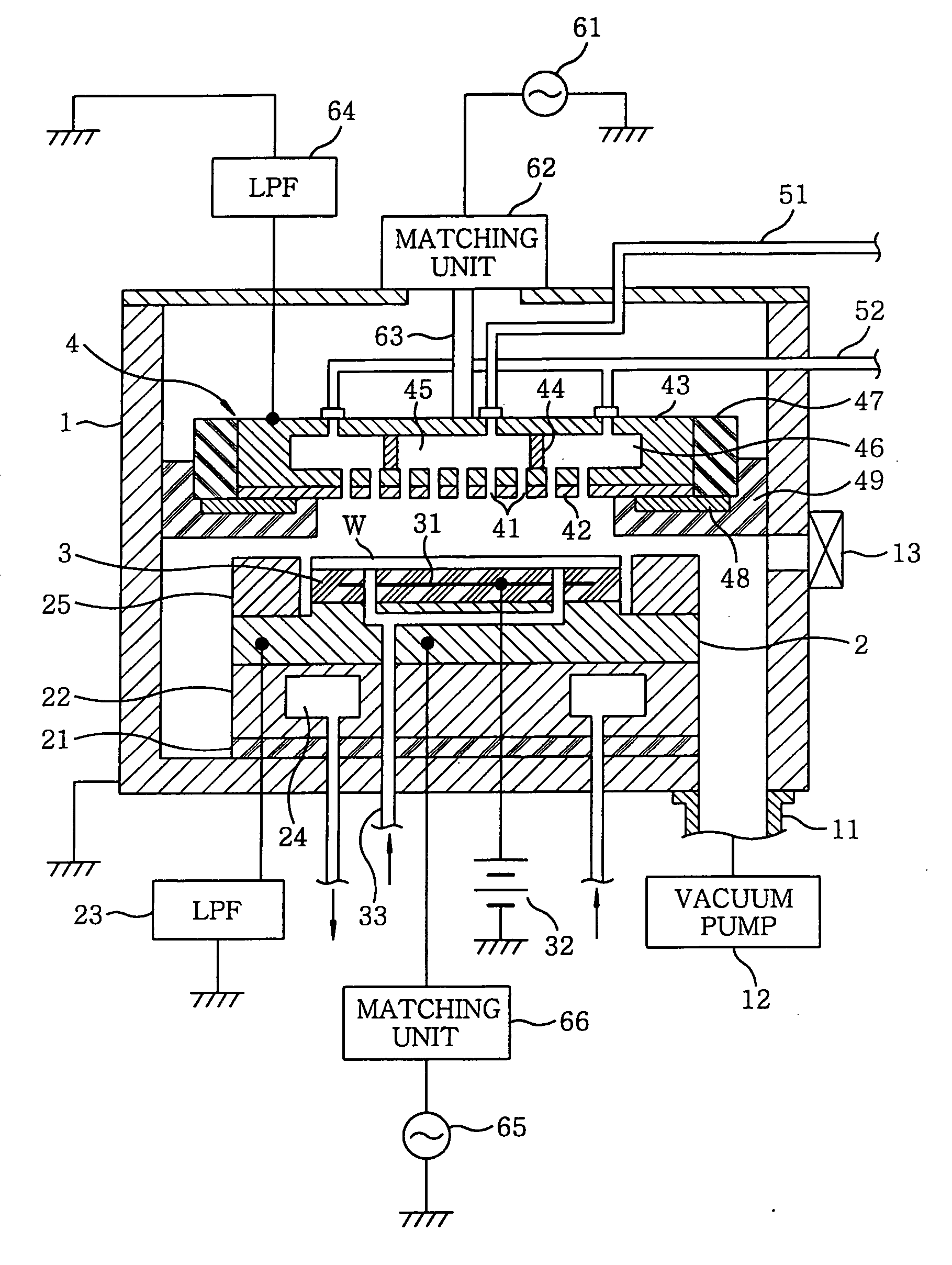
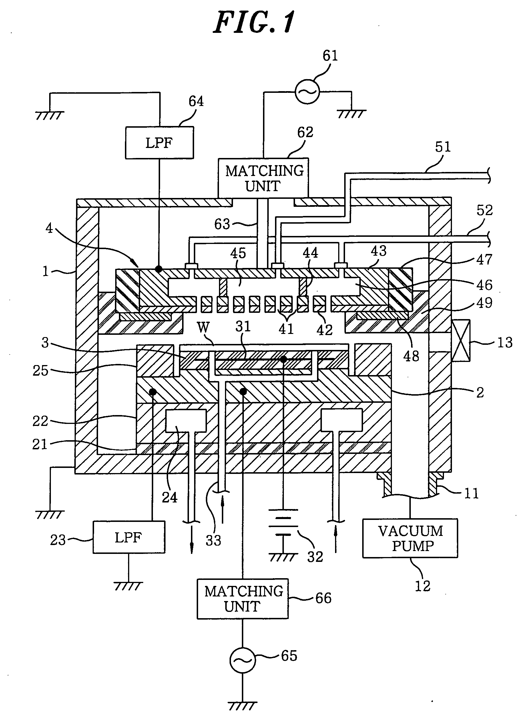
[0113] After the processing gas was produced in advance by mixing CHF3 gas employed as the CF-based gas; and Ar gas and N2 gas employed as the dilution gas, an etching process was performed on a resist layer (formed on an entire surface of the wafer W without patterns formed thereon) formed on the wafer W under the following processing condition by introducing the processing gas into the plasma etching apparatus shown in FIG. 1 while varying the amounts of the processing gases supplied to the central portion and the peripheral portion of the gas supply surface. Then, the in-surface uniformity of CF density and CF2 density on the wafer W was measured by utilizing an LIF (laser induced fluorescence) technology. The flow rate ratios C / E of the processing gases were set to be 0 / 10, 3 / 7, 5 / 5, 7 / 3 and 10 / 0. Further, the flow rate ratio C / E of 0 / 10 means a case where the processing gas is supplied only to the peripheral portion of the gas supply surface.

[0114][0115] Flow rate ratio of CHF...

embodiment 2

[0122] After the processing gas was produced in advance by mixing CHF3 gas employed as the CF-based gas; and Ar gas and N2 gas employed as the dilution gas, an etching process was performed on an etching target film (SiOC film) formed on the wafer W under the following processing condition by introducing the processing gas into the plasma etching apparatus shown in FIG. 1 while varying the flow rates of the processing gases supplied to the central portion and the peripheral portion of the gas supply surface. Then, the in-surface uniformity of a residual resist film, an etching depth, a top CD and a bowing position was evaluated. Here, the flow rate ratios C / E of the processing gases supplied to the central portion and the peripheral portion of the gas supply surface were set to be 1 / 9, 5 / 5 and 9 / 1.

[0123] In FIG. 8A, a reference numeral 71 refers to the SiOC film serving as the etching target film; and a reference numeral 72 refers to a resist film formed on the surface of the SiOC ...

embodiment 3

[0131] After the processing gas was produced in advance by mixing CHF3 gas employed as the CF-based gas; and Ar gas, N2 gas and O2 gas employed as the dilution gas, an etching process was performed on an etching target film (SiOCH film) formed on the wafer W under the following processing condition by introducing the processing gas into the plasma etching apparatus shown in FIG. 1 while varying the flow rates of the processing gases supplied to the central portion and the peripheral portion of the gas supply surface. Then, the in-surface uniformity of the top CD and the etching depth formed by etching was evaluated.

[0132][0133] Processing pressure; 6.65 Pa (50 mTorr) [0134] Frequency and power of the first high frequency power supply 61; 60 MHz, 1500 W [0135] Frequency and power of the second high frequency power supply 65; 2 MHz, 2800 W

[0136]FIGS. 9A and 9B show the in-surface uniformity of the top CD and the in-surface uniformity of the etching depth, respectively. In FIG. 9A, t...


PUM

PropertyMeasurementUnit
DC voltageaaaaaaaaaa
pressureaaaaaaaaaa
frequencyaaaaaaaaaa

Abstract

When a substrate is etched by using a processing gas including a first gas containing halogen and carbon and having a carbon number of two or less per molecule, while supplying the processing gas toward the substrate independently from a central and a peripheral portion of a gas supply unit, which face the central and the periphery part of the substrate respectively, the processing gas is supplied such that a gas flow rate is greater in the central portion than in the peripheral portion. When the substrate is etched by using a processing gas including a second gas containing halogen and carbon and having a carbon number of three or more per molecule, the processing gas is supplied such that a gas flow rate is greater in the peripheral portion than in the central portion.

Description

CROSS-REFERENCE TO RELATED APPLICATIONS [0001] This document claims priority to Japanese Patent Application Number 2005-87889, filed Mar. 25, 2005 and U.S. Provisional Application No. 60 / 666,574, filed Mar. 31, 2005, the entire content of which are hereby incorporated by reference.FIELD OF THE INVENTION [0002] The present invention relates to a technology for performing an etching on an etching target film formed on a substrate such as a semiconductor wafer by using a gas containing carbon and halogen. BACKGROUND OF THE INVENTION [0003] In a manufacturing process of a semiconductor device or an LCD substrate, an etching process is performed to form a pattern of a thin film. As one of a variety of etching apparatuses, for example, there is a parallel plate plasma etching apparatus, wherein parallel plate electrodes including a pair of an upper and a lower electrode are disposed in a chamber, and a high frequency electric field is formed therebetween by applying a high frequency power...

Claims


Application Information

Patent Timeline
Patent Type & Authority Applications(United States)
IPC IPC(8): C03C25/68G01L21/30H01L21/306
CPCH01J37/32935H01L21/30604H01L21/31138H01L21/31116
Inventor TAHARA, SHIGERUNISHINO, MASARU
Owner TOKYO ELECTRON LTD
Why Eureka
Try Eureka