Light emitting diodes and methods of fabrication

a technology of light-emitting diodes and fabrication methods, which is applied in the direction of basic electric elements, electrical apparatus, and semiconductor devices, can solve the problems of significant number of defects introduced into the semi-conducting layer, difficult subsequent processing, and high cost and limited efforts, so as to achieve real depth tolerance, prevent cracking and chipping, and be sufficiently robust

Inactive Publication Date: 2006-09-28
GOLDENEYE
View PDF7 Cites 87 Cited by
  • Summary
  • Abstract
  • Description
  • Claims
  • Application Information

AI Technical Summary

Benefits of technology

[0017] These embodiments are enabled by the use of thicker layers available from HVPE type growths. In this case, there exists sufficient thickness within the device such that adequate contact area can be formed on the edges or sides of the die. In addition, the thicker layers enable the use of laser ablation techniques. Typically tolerances on the order of a micron or less are needed in such p

Problems solved by technology

Due to thermal expansion effects at high deposition temperatures and lattice mismatches between the semiconducting layer and the growth substrate, a significant number of defects are introduced into the semiconducting layers during deposition.
These efforts are still very expensive and limited by the size of the freestanding wafer.
The stresses in such layers, however, lead to strains such as wafer bowing that make subsequent processing difficult, especially if traditional planar lithography or wafer-bonding steps are required.
LED dies produced by the laser liftoff process suffer, however, from significant current spreading issues due to lack of an attached electrically conductive substrate and the thinness of the semiconductor layers.
The lateral growth process can make high-quality, small devices a few microns wid

Method used


Image

  • Light emitting diodes and methods of fabrication
  • Light emitting diodes and methods of fabrication
  • Light emitting diodes and methods of fabrication

Examples


Embodiment Construction

[0042] The preferred embodiments of the present invention will be better understood by those skilled in the art by reference to the above figures. The preferred embodiments of this invention illustrated in the figures are not intended to be exhaustive or to limit the invention to the precise form disclosed. The figures are chosen to describe or to best explain the principles of the invention and its applicable and practical use to thereby enable others skilled in the art to best utilize the invention.

[0043] The figures are not drawn to scale. In particular, the thickness dimension is expanded relative to the length and width dimensions in order to clearly illustrate the multiple layers of the devices.

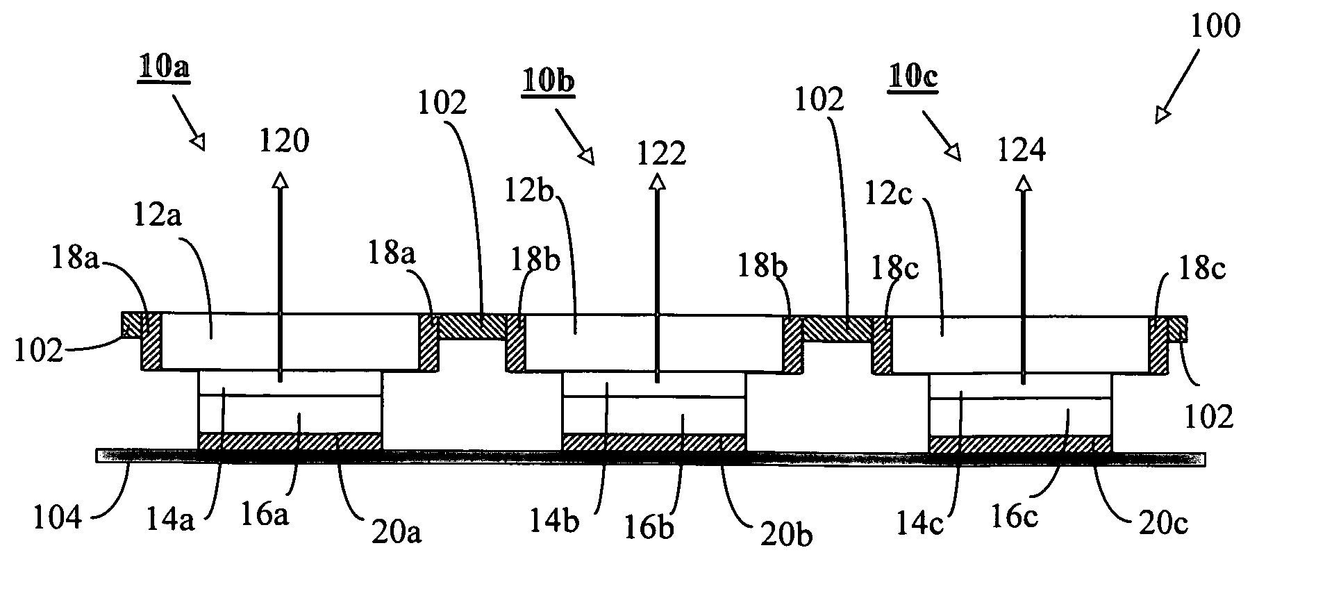
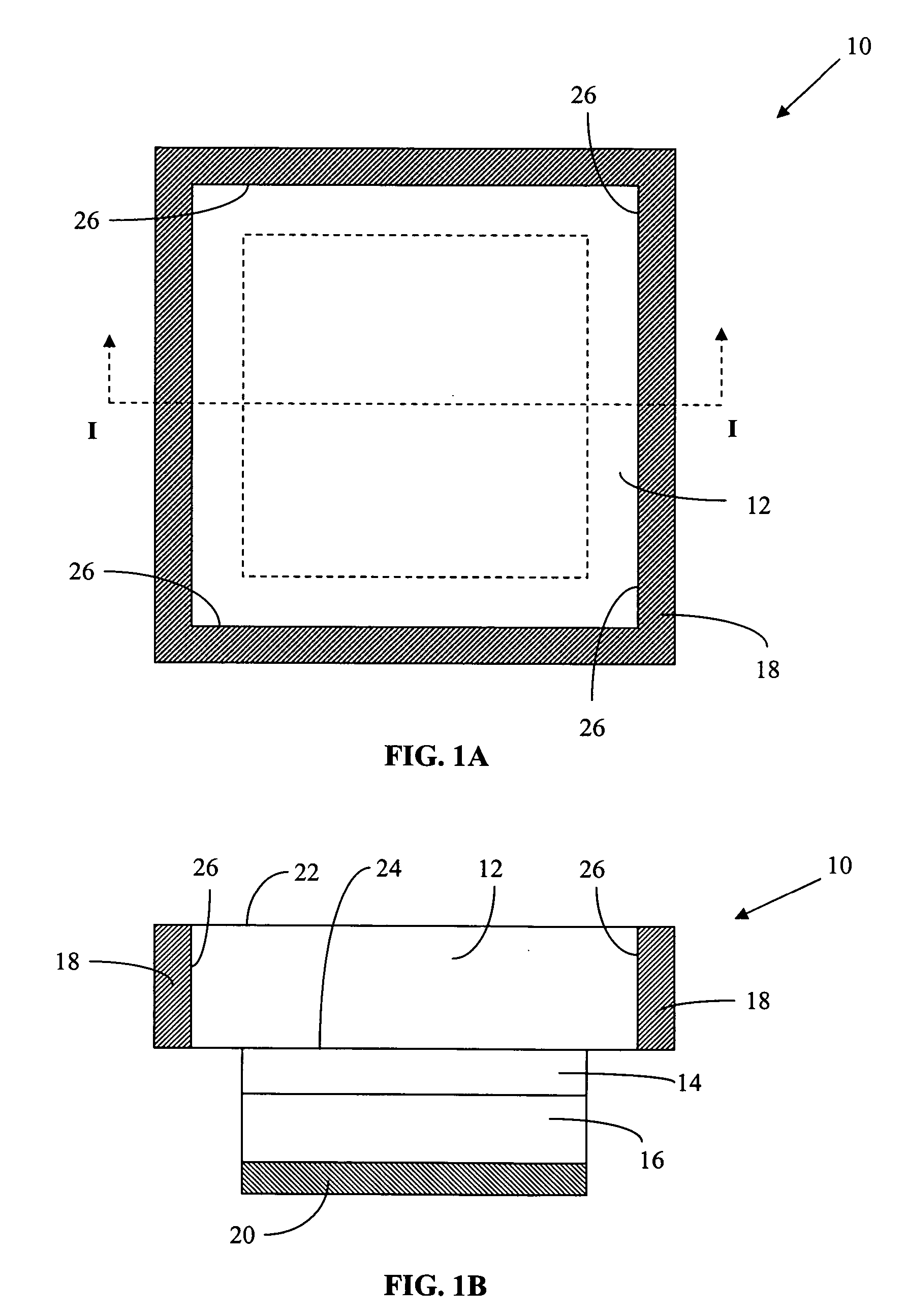
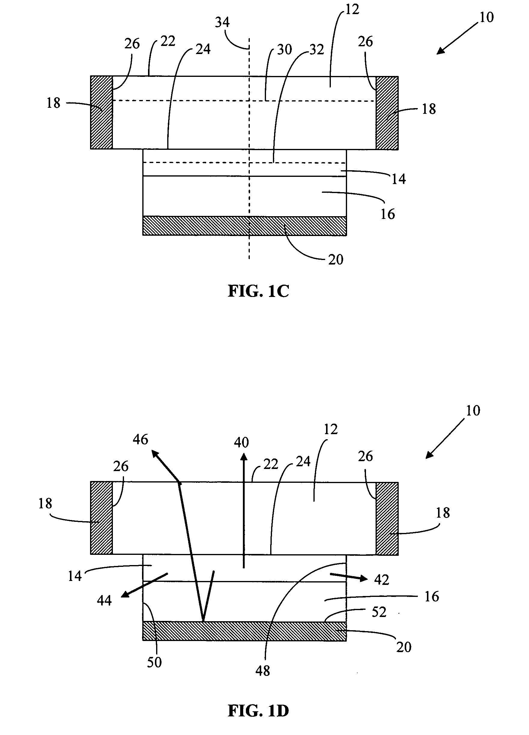
[0044]FIGS. 1A-1D illustrate one embodiment of this invention. FIG. 1A is a plan view of light emitting diode 10 of this invention and FIGS. 1B-1D are cross-sectional views of light emitting diode 10 along the I-I plane illustrated in FIG. 1A. Light emitting diode 10 is comprised of a...


PUM


Abstract

A light emitting diode includes a first doped semiconductor layer, an active region and a second doped semiconductor layer. The sectional area of the active region is less than the sectional area of the first doped semiconductor layer. One electrode of the light emitting diode is connected to the edge surfaces of the first doped semiconductor layer. The second electrode is connected to the second doped semiconductor layer. A method is described for fabricating the light emitting diode.

Description

[0001] This application claims the benefit under 35 USC § 119(e) of U.S. Provisional Application No. 60 / 665,898, filed Mar. 28, 2005, the contents of which is hereby incorporated by reference in its entirety.FIELD OF THE INVENTION [0002] The present invention relates to light emitting diodes and to methods for fabricating light emitting diodes. BACKGROUND OF THE INVENTION [0003] Light emitting diodes can be fabricated by depositing one or more layers of a semiconductor material onto a growth substrate. Deposition methods can include chemical vapor deposition (CVD), metal-organic chemical vapor deposition (MOCVD), molecular beam epitaxy MBE), liquid phase epitaxy (LPE) and vapor phase epitaxy (VPE). When a layer of semiconductor material is deposited onto a growth substrate, tensile or compressive stresses can occur that affect the planarity of the deposited film and the growth substrate as well as the electrical and optical properties of the semiconductor layer. [0004] In one exampl...

Claims


Application Information

Patent Timeline
IPC IPC(8): H01L33/00H01L33/14H01L33/20H01L33/38H01L33/62
CPCH01L25/0753H01L33/0079H01L33/14H01L33/20H01L33/38H01L33/385H01L33/507H01L33/62H01L2924/0002H01L2924/00H01L33/0093
Inventor BEESON, KARL W.ZIMMERMAN, SCOTT M.
Owner GOLDENEYE
Why Eureka
Try Eureka