
System and method for pattern design in microwave programmable arrays

a technology of programmable arrays and patterns, which is applied in the field of system and method of pattern design in microwave programmable arrays, can solve the problems of reducing the signal-to-noise ratio (snr) patterns may not be optimal for various parameters of the microwave imaging system, and patterns may not be optimal for reducing background noise at the microwave receiver, so as to achieve faster processing of pattern data and small storage space

Active Publication Date: 2006-09-28
AGILENT TECH INC
View PDF37 Cites 29 Cited by
  • Summary
  • Abstract
  • Description
  • Claims
  • Application Information

AI Technical Summary

Benefits of technology

[0011] In a further embodiment, the parameter to be optimized is a ratio of a main lobe area to side lobe areas of the beam of microwave radiation at the target. In still a further embodiment in which the selected phase shifts for each of the antenna elements form a pattern, the parameter to be optimized is a metric associated with the digital compression of the pattern description in bits, which allows for a smaller storage space and faster handling of the pattern data.

Problems solved by technology

However, each pattern design is largely dictated by the frequency of the microwave radiation and the orientation of the antenna elements in the array to one or more of a microwave source (if applicable), microwave receiver (if applicable) and a particular target, and therefore, the patterns may not be optimal for various parameters of the microwave imaging system.
For example, background noise (often referred to as “clutter”) that results from stray radiation from the microwave source to the microwave receiver reduces the signal-to-noise ratio (SNR) of the microwave imaging system.
Although a particular pattern may create the desired constructive interference at the target, that pattern may not be optimal to reduce the background noise at the microwave receiver.
As another example, the phase changes between a pair of patterns used in scanning a person or other object may cause sidelobes that increase in area as the antenna phasing changes.

Method used


Image

  • System and method for pattern design in microwave programmable arrays
  • System and method for pattern design in microwave programmable arrays
  • System and method for pattern design in microwave programmable arrays

Examples


Embodiment Construction

[0025] As used herein, the terms microwave radiation and microwave illumination each refer to the band of electromagnetic radiation having wavelengths between 0.3 mm and 30 cm, corresponding to frequencies of about 1 GHz to about 1,000 GHz. Thus, the terms microwave radiation and microwave illumination each include traditional microwave radiation, as well as what is commonly known as millimeter-wave radiation.

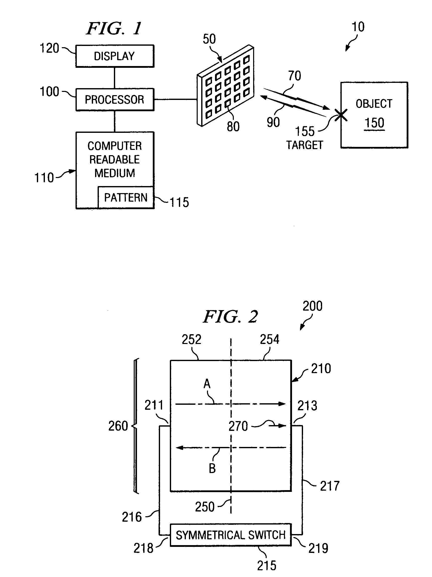
[0026]FIG. 1 is a schematic diagram of a simplified exemplary microwave imaging system 10, in accordance with embodiments of the present invention. The microwave imaging system 10 includes a one or more arrays 50 (only one of which is shown for convenience), each capable of transmitting, receiving and / or reflecting microwave radiation via antenna elements 80 to capture a microwave image of an object 150 (e.g., suitcase, human subject or any other item of interest).

[0027] In one embodiment, the array 50 includes a passive programmable reflector array composed of reflecting ant...


PUM


Abstract

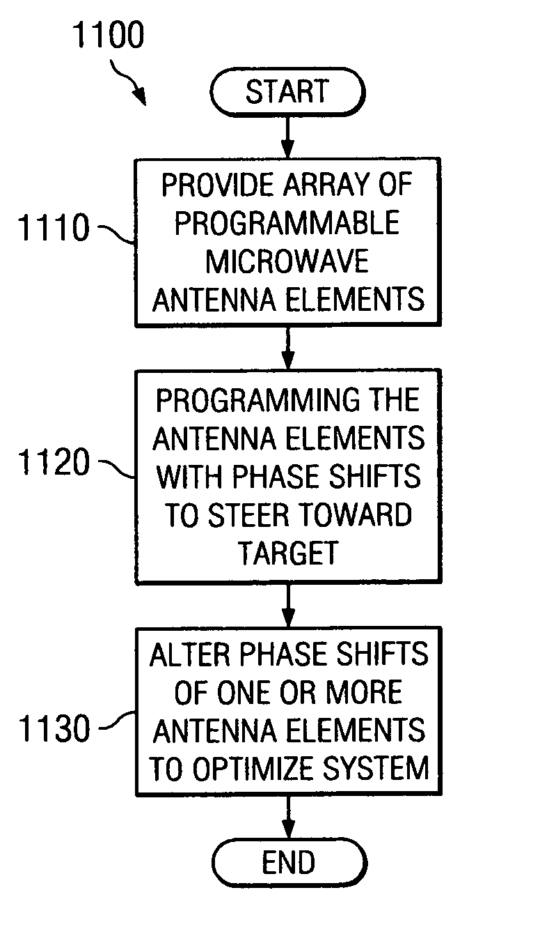
An antenna array for use within a microwave imaging system to capture a microwave image of a target is selectively programmed to optimize one or more parameters of the microwave imaging system. The array includes a plurality of antenna elements, each capable of being programmable with a respective phase shift to direct a beam of microwave radiation toward the target such that the microwave radiation from each of the plurality of antenna elements arrives at the target substantially in-phase. To optimize a parameter of the microwave imaging system, the phase shifts of selective ones of the antenna elements are altered, while still maintaining the substantially in-phase microwave radiation at the target.

Description

CROSS-REFERENCE TO RELATED APPLICATIONS [0001] This application is related by subject matter to U.S. application patent Ser. No. ______ (Attorney Docket No. 10040151), entitled “A Device for Reflecting Electromagnetic Radiation,” U.S. application patent Ser. No. ______ (Attorney Docket No. 10040580), entitled “Broadband Binary Phased Antenna,” and U.S. application patent Ser. No. ______ (Attorney Docket No. 10040142), entitled “System and Method for Security Inspection Using Microwave Imaging” all of which were filed on Nov. 24, 2004. [0002] This application is further related by subject matter to U.S. application patent Ser. No. ______ (Attorney Docket No. 10050095), entitled “System and Method for Efficient, High-Resolution Microwave Imaging Using Complementary Transmit and Receive Beam Patterns,” U.S. application patent Ser. No. ______ (Attorney Docket No. 10050215), entitled “System and Method for Inspecting Transportable Items Using Microwave Imaging,” U.S. application patent S...

Claims


Application Information

Patent Timeline
IPC IPC(8): G01S13/89
CPCG01S13/89H01Q3/46H01Q1/38H01Q3/26
Inventor BAHARAV, IZHAKTABER, ROBERT C.LEE, GREGORY S.
Owner AGILENT TECH INC
Learn More