Microarrayer with coaxial multiple punches

Inactive Publication Date: 2006-09-28
GEBING RONALD A
View PDF6 Cites 44 Cited by
  • Summary
  • Abstract
  • Description
  • Claims
  • Application Information

AI Technical Summary

Benefits of technology

[0017] The invention is an improved microarrayer for constructing biological arrays in an embedding medium. The improved microarrayer is less complex and more efficient than known microarrayers. The

Problems solved by technology

Although the method arrays multiple tissue samples, the method requires a high degree of manual dexterity, and often makes it difficult to find and identify particular samples of interest.
This method has improved the ability to identify the location of samples but is still very time consuming and is performed manually.
The device requires an offset measurement sensor, and efficiency is reduced by the subsequent measurement and correction times.
But the time, however small, to locate a punch, grip, and move to the desired location for oper

Method used


Image

  • Microarrayer with coaxial multiple punches
  • Microarrayer with coaxial multiple punches
  • Microarrayer with coaxial multiple punches

Examples


first embodiment

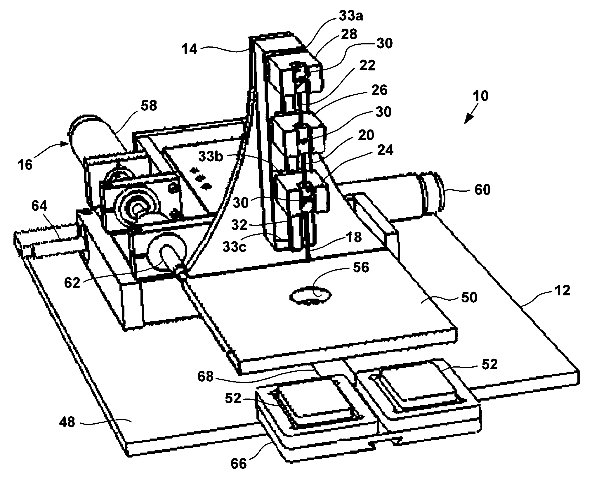
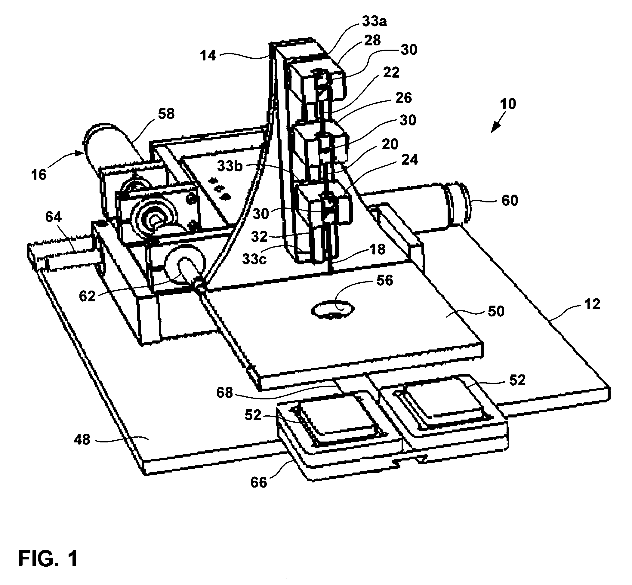
[0039]FIG. 1 illustrates a first embodiment microarrayer 10 in accordance with the present invention. Microarrayer 10 constructs arrays of biological material from donor cores obtained from at least one donor block, placing the donor cores in an embedding medium carried by at least one recipient block. The recipient and donor blocks are supported on a fixed support platform 12 that defines an X-Y plane. Extending away from the support platform 12 in the Z-direction is a punch platform 14. Punch platform 14 is stationary with respect to support platform 12 in the Z-direction, but is movable relative to the support platform in the X and Y directions by a platform drive assembly 16. Drive 16 displaces the punch platform 14 in the X and Y directions to selectively position the platforms 12, 14 with respect to one another.

[0040] Mounted on the punch platform 14 is a donor punch 18, a recipient punch 20, and a stylus 22. Each of the punches 18, 20 and stylus 22 are movably mounted on the ...

second embodiment

[0062] In a second embodiment, drive assembly 16 can be under automatic control to automatically move and position the punch platform 14 to form the array of receptacles in a recipient block or to move between a donor block coring position to the next recipient block coring position.

[0063]FIG. 10 illustrates a second microarrayer 110 in accordance with the present invention. Microarrayer 110 is otherwise identical to microarrayer 10 but includes a computerized control system 112 having a user interface represented by a display screen 114 and operatively coupled to drive assembly 16 and drives 116, 118, and 120 that drive the donor punch slide, recipient punch slide, and the stylus slide respectively. Pneumatic, hydraulic, and electric slide drives are known and can be readily adapted for use in the present invention.

[0064] Control system 112 automatically controls the drives and motors and responds to user feedback received from a keypad, mouse, stylus, touch screen, or the like, a...


PUM


Abstract

A microarrayer apparatus for constructing arrays of biological material from donor cores obtained from at least one donor block and placing the donor cores in an embedding medium carried by at least one recipient block. The apparatus includes a donor punch, a recipient punch, and a stylus mounted for independent coaxial movement along a common punch axis. The recipient punch cooperates with the stylus when ejecting a donor core from the donor punch to minimize deformation of the donor core.

Description

[0001] This application claims priority to U.S. Provisional Patent Application No. 60 / 664,539 filed Mar. 23, 2005.FIELD OF INVENTION [0002] The invention relates to an apparatus for the construction of biological arrays in an embedding medium, namely, an apparatus capable of creating paraffin-embedded biological arrays as well as frozen biological arrays. BACKGROUND OF INVENTION [0003] Researchers at the National Human Genome Research Institute (NHGRI) at the National Institutes of Health (NIH), in collaboration with the University of Tampere in Finland and the University of Basel in Switzerland, have developed a new research tool which they call the “tissue chip.” The tissue chip has enabled researchers to distinguish among subgroups of cancer patients and eventually predict which subgroups will respond to specific therapies. Such detailed new information can then be used to identify critical molecules for development of cancer therapies. [0004] The tissue chip is a thin section of...

Claims


Application Information

Patent Timeline
IPC IPC(8): G01N33/48C12M1/36
CPCC12M1/165G01N1/36G01N2001/288G01N2001/368
Inventor GEBING, RONALD A.
Owner GEBING RONALD A
Why Eureka
Try Eureka