Telescoping vascular dilator

a vascular dilator and telescoping technology, applied in the field of vascular dilators, can solve the problems of dilators and sheaths, dilators described in the prior art, and large intravascular devices of a special challenge for minimally invasive insertion, and achieve the effect of minimal blood loss and minimal invasiveness

Inactive Publication Date: 2006-09-28
HATTLER BRACK G +1
View PDF29 Cites 85 Cited by
  • Summary
  • Abstract
  • Description
  • Claims
  • Application Information

AI Technical Summary

Benefits of technology

[0011] Briefly and in general terms, the present invention provides a dilator assembly that allows large intravascular devices to be percutaneously passed into a blood vessel or other body cavity without the need for a surgical incision and with minimal blood loss during dilation of the blood vessel. The present invention further provides a dilator and sheath combination that allows large intravascular devices to be percutaneously passed into a blood vessel or other body cavity through the sheath without the need for a surgical incision. ...

Problems solved by technology

Larger diameter intravascular devices present a special challenge for minimally invasive insertion into a blood vessel without a surgical “cut down” to the vessel.
Problems with the prior art dilators and sheaths occur when a very large diameter sheath is required to insert large diameter medical devices into a blood vessel.
Dilators described in the prior art have problems when used for insertion of such a large sheath and large diameter medical device into a venous structure.
One problem is that the guidewire may kink, bend, knot, or otherwise be damaged within the large inner channel within the dilator.
The guidewire may still be subject to kinking.
Therefore, the described devices do not solve the problem of how to safely use a dilator with a medical device requiring a very large sheath.
The known pri...

Method used


Image

  • Telescoping vascular dilator
  • Telescoping vascular dilator
  • Telescoping vascular dilator

Examples


Embodiment Construction

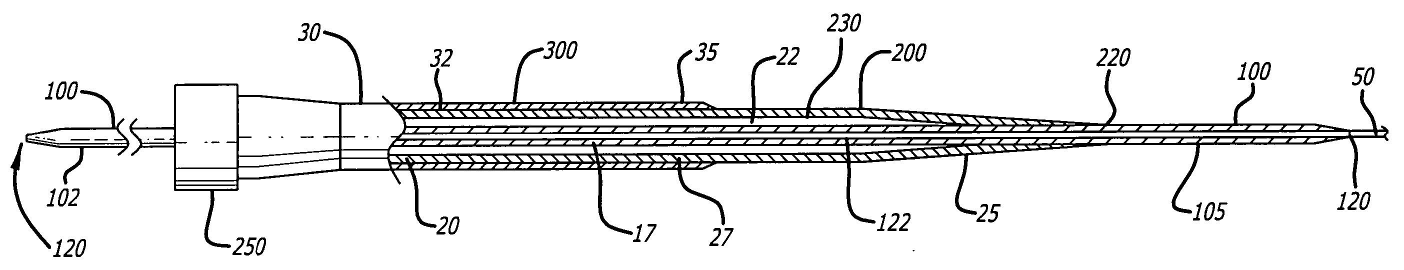
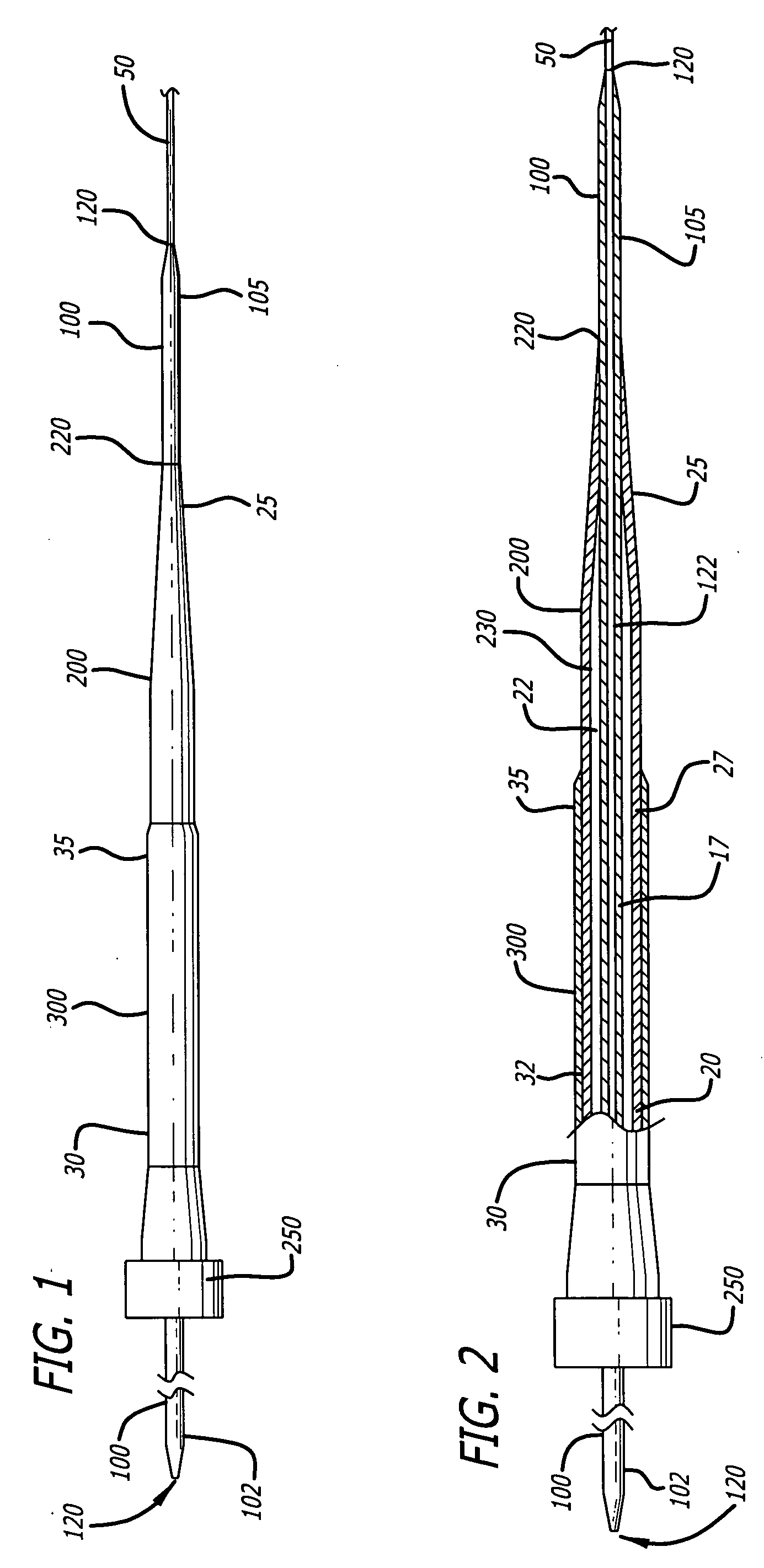
[0043] Referring to FIGS. 1 and 2, the present invention includes at least one larger diameter dilator 200 that may be circumferentially and telescopically passed over at least one smaller diameter dilator 100. The smaller diameter dilator 100 may be circumferentially passed over a guidewire 50 that has been percutaneously inserted into a blood vessel. Because an inner channel 122 of the smaller diameter dilator fits snugly around the guidewire 50, once the smaller diameter dilator 100 has been passed over the guidewire 50, the guidewire 50 may be prevented from kinking. The larger diameter dilator 200 can then safely be passed over the smaller diameter dilator 100. The larger diameter dilator 200 may be further detachably connected with a sheath 300 by a fitting 250 that detachably locks the larger diameter dilator 200-and sheath 300 together in position for insertion into the blood vessel. The larger diameter dilator 200 is capable of being unlocked from the sheath 300 after inser...


PUM


Abstract

A telescoping dilator assembly is configured for percutaneous insertion of large diameter intravascular devices into a blood vessel while avoiding kinking of a guidewire and minimizing blood loss. The assembly includes a first smaller diameter dilator with an inner lumen that fits snugly over a guidewire. The smaller dilator may be tapered on both ends. A second larger diameter dilator is configured to slide over the first smaller dilator. A tear away sheath is configured to slide over the dilators and into a blood vessel. A tear away sheath plug is configured to form a seal at a proximal end of the sheath. When the dilators are removed from the blood vessel, an intravascular device may be passed through the sheath into the blood vessel.

Description

CROSS-REFERENCES TO RELATED APPLICATION [0001] This application claims priority to U.S. Provisional Patent Application Ser. No. 60 / 628,309 filed Nov. 15, 2004 entitled HEMOSTASIS DILATOR, the entire contents of which are incorporated herein by reference.FEDERALLY SPONSORED RESEARCH [0002] The U.S. Government has a paid-up license in this invention and the right in limited circumstances to require the patent owner to license others on reasonable terms as provided for by the terms of Grant Nos. DAMD 17-03-1-0512 awarded by the Department of the Army.BACKGROUND OF THE INVENTION [0003] This invention relates to the field of dilators used for insertion of medical instruments and devices into the body. More specifically, this invention relates to a system of vascular dilators, wherein one dilator may be telescopically inserted over another smaller diameter dilator, thereby slowly enlarging an entry point into the body. The invention is useful for establishing intravascular access for inse...

Claims


Application Information

Patent Timeline
IPC IPC(8): A61M5/178
CPCA61M25/0668A61M29/00A61M2025/0175
Inventor HATTLER, BRACK G.TESTA, VINCENT J.
Owner HATTLER BRACK G
Why Eureka
Try Eureka