
Assembly for aspiration and/or dispensing of organisms and fluids

a technology for aspiration and/or dispensing of organisms and fluids, which is applied in the direction of intravenous devices, medical syringes, syringes, etc., can solve the problems of small plunger movement and difficulty in achieving

Inactive Publication Date: 2006-09-28
COOPERSURGICAL INC
View PDF1 Cites 41 Cited by
  • Summary
  • Abstract
  • Description
  • Claims
  • Application Information

AI Technical Summary

Benefits of technology

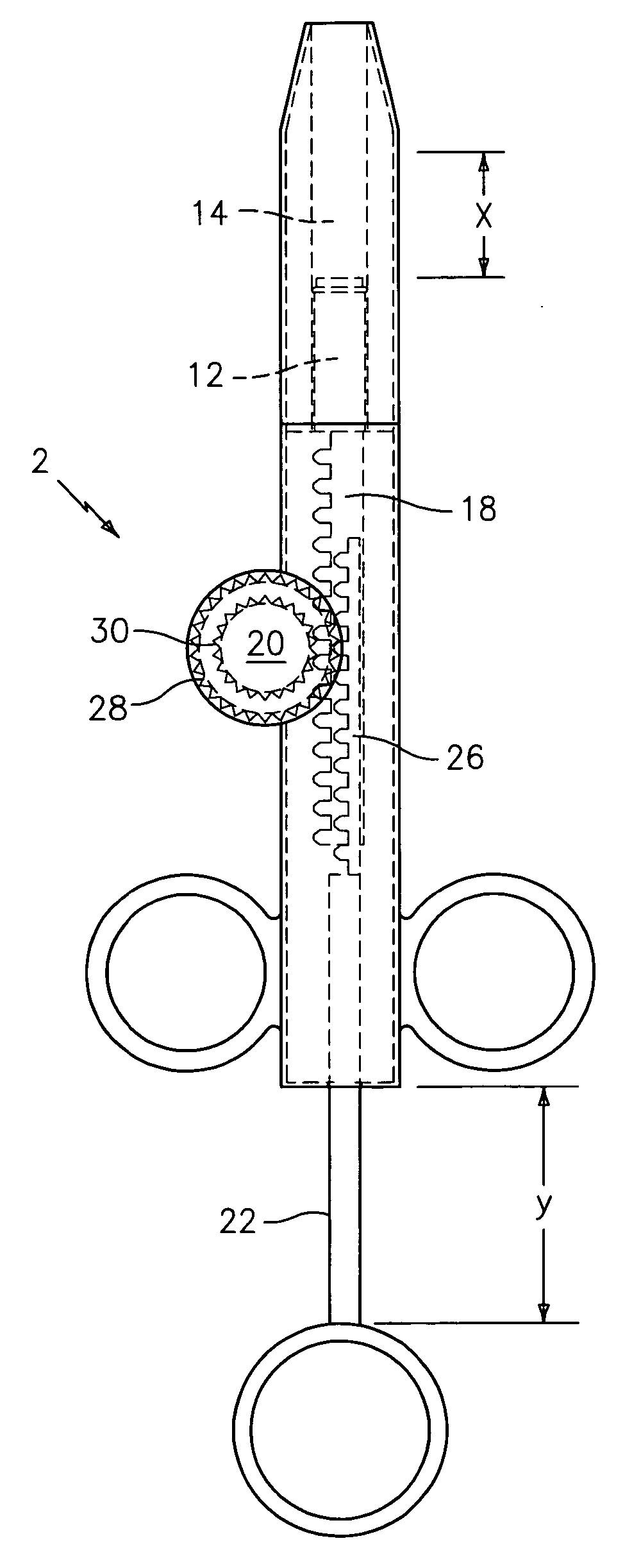
[0010] This invention relates to an improved syringe assembly that utilizes gears or sets of gears. The syringe of this invention includes gears, a plunger, a thumb actuator assembly and an outer syringe-shaped housing. By using gears or sets of gears as a link between the thumb actuator and the plunger, the syringe can be used to draw or dispense fluids, and to draw a vacuum or create pressure when the thumb assembly and plunger assembly are drawn at different ratios, rates, or lengths. In one embodiment of the syringe assembly, a gear or gear set serves as the link and allows the drawing of a small vacuum at the plunger end of the assembly by moving the plunger a short distance while the thumb assembly is moved a longer more easily ergonomically attainable distance, which enables greater accuracy and ease of use of the syringe assembly.
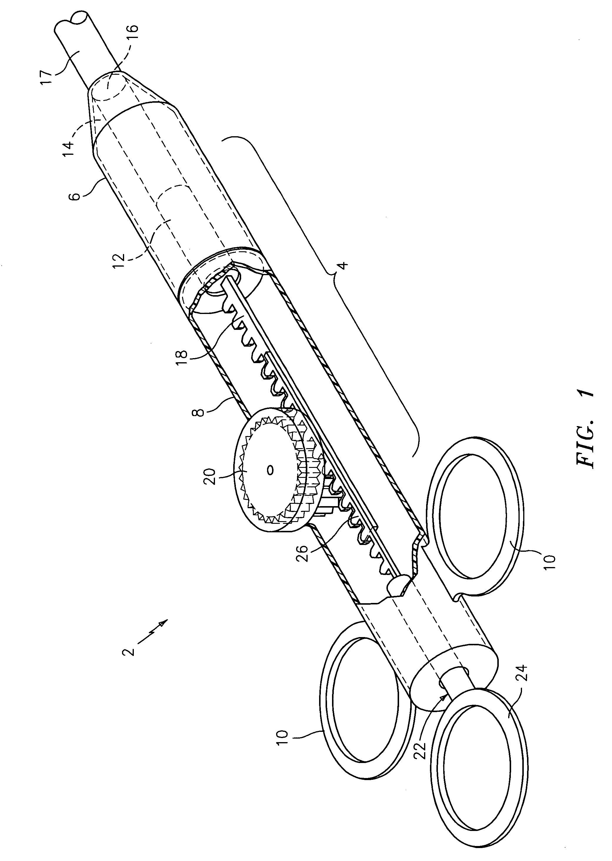
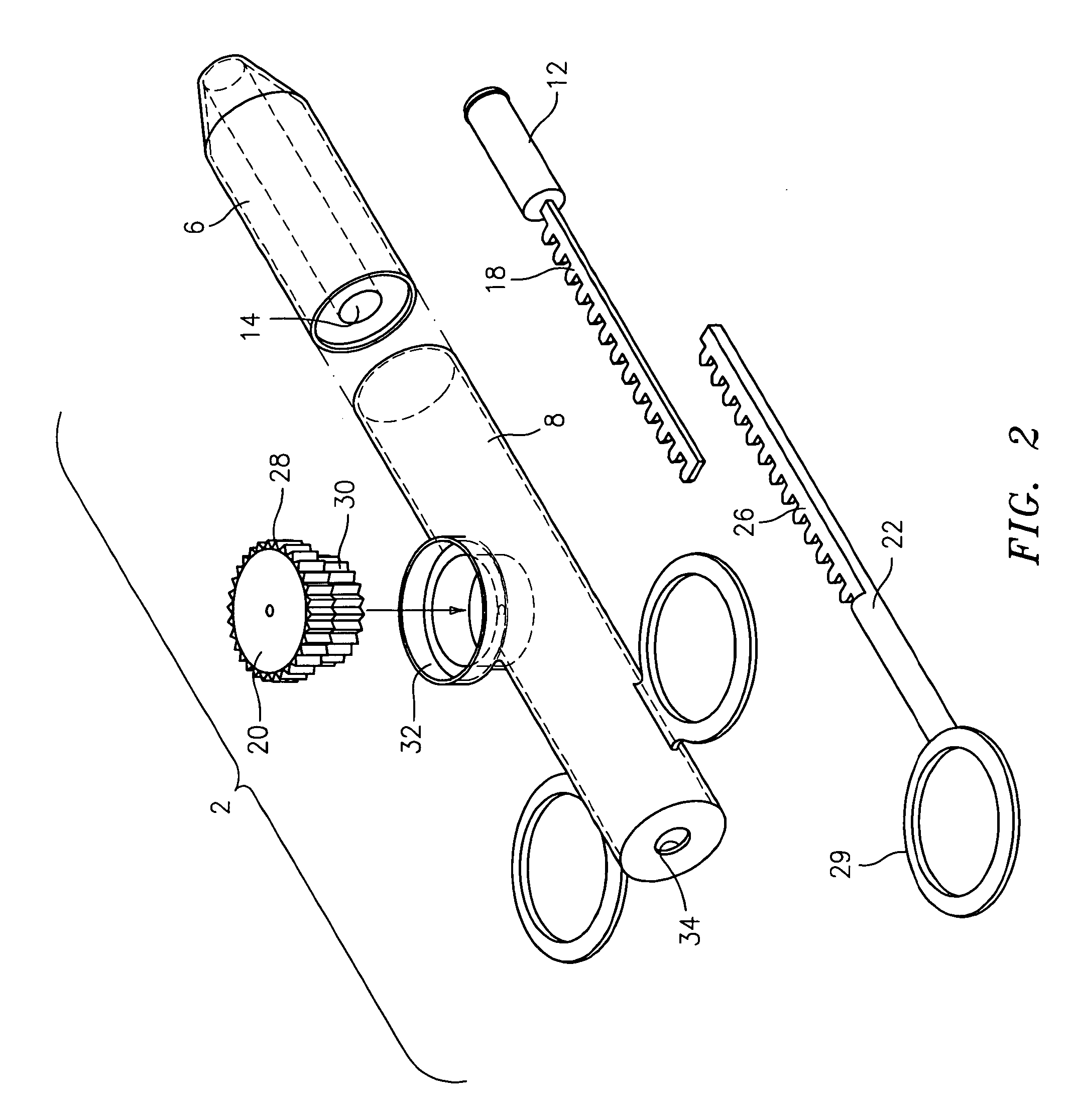
[0013] In one embodiment of the device, the front portion cavity can have a 0.090″ inner diameter, which is greater than the 0.060″ inner diameter of an aspiration catheter to which the syringe assembly is connected. The extension portion of the plunger engages the link assembly to allow the plunger assembly to move in synchronization with the link. The subassembly parts will be inserted into a body assembly to complete the unit. The thumb portion extension also engages the link, so that linear movement of the thumb portion of the assembly rotates the link which in turn causes linear movement of the plunger component of the assembly. The link will have different diameter components, so as to result in the thumb and plunger parts of the assembly moving different distances when the thumb part is either pulled or pushed. For example, the operator may draw on the thumb assembly for a distance of three centimeters. The thumb assembly would then turn the first portion of the link it is in contact with. This first portion of the link is attached to or is in contact with a second portion of the link which has a smaller diameter than the first portion. As the first portion turns, it, in turn, turns the second portion. The second portion in turn moves the plunger in the front of the device so as to create suction in the front cavity. This in turn will create suction in the attached tubing or catheter, which will in turn draw air or fluids into the catheter, accomplishing what it was set out to do. Thus, depending on the ratio of the link portion diameters, the extent of movement of the plunger, and thus the positive or negative pressure created thereby, will be a fraction of the extent of movement of the thumb part of the assembly. Thus an easily accomplished extent of movement of the thumb piece will result in a smaller extent of movement of the plunger which would be difficult to accomplish with a one to one movement ratio between the thumb part and the plunger part. Thus, a small degree of suction can be applied to the catheter by the plunger as the result of an ergonomically easily accomplished thumb part stroke.
[0014] The assembly of this invention will allow the making of syringe assemblies that will be usable for applications such as the transferring of embryos or sperm. The advantage is that the technician may draw the thumb assembly a workable ergonomic distance, such as three centimeters, to, in turn draw the frontal plunger assembly only one centimeter. The size of the plunger diameter can also differ from that of the thumb assembly and that of the catheter.
[0017] The assembly of this invention may be used to dispense fluids or to create a vacuum to aspirate fluids or tissue. This may be done by assembling the plunger and thumb parts of the assembly and the extensions on these parts on the same or opposite sides of the link assembly. By placing the plunger assemblies in this way, one plunger might withdraw as one plunger advances, therefore allowing the dispersing and intake to occur at the same time.

Problems solved by technology

Thus an easily accomplished extent of movement of the thumb piece will result in a smaller extent of movement of the plunger which would be difficult to accomplish with a one to one movement ratio between the thumb part and the plunger part.

Method used


Image

  • Assembly for aspiration and/or dispensing of organisms and fluids
  • Assembly for aspiration and/or dispensing of organisms and fluids
  • Assembly for aspiration and/or dispensing of organisms and fluids

Examples


Embodiment Construction

[0026]FIG. 1 is a perspective view of one embodiment of a syringe assembly, which is denoted generally by the numeral 2, and which is formed in accordance with this invention. The syringe assembly 2 includes an outer barrel component 4 which may include two interconnected parts 6 and 8, or which may be formed as one unitary part. The barrel 4 may include opposed optional finger rings 10. A plunger 12 is disposed in a bore 14 in the barrel 4. The bore 14 forms an opening 16 at one end of the barrel 4 into which opening 16 an aspirating catheter 17 can be snugly inserted. The plunger 12 is reciprocally movable in the bore 14. A gear toothed rack 18 extends from and is connected to the plunger 12. It will be appreciated that movement of the plunger 12 in the bore 14 is what creates a positive or negative pressure in the bore 14. The assembly 2 also includes a reciprocating thumb piece 22, which may have an optional thumb ring 24, and which has a rack 26 which extends from and is connec...


PUM


Abstract

An assembly for the drawing or dispensing of materials by utilizing a gear or gear system provides an ergonomically superior device. The gear system in the assembly may allow the assembly to dispense materials or create a vacuum for multiple tasks at the same time. The materials may be dispensed in various or different volumes simultaneously by the assembly. The assembly will also allow the creation of a vacuum and dispensing of fluids at the same time. The assembly will enable dispensing fluids in various ratios or creating a vacuum or pressure, or both simultaneously. The assembly results in a more ergonomically suitable syringe and / or dispenser for the user.

Description

TECHNICAL FIELD [0001] This invention relates to an assembly, for the dispensing of fluids or creation of a vacuum of differing and various ratios. More particularly, the assembly of this invention is especially useful for dispensing of small amounts of fluids, or for creating a vacuum, from or in a small volume catheter or pipette. BACKGROUND ART [0002] Syringes are generally used either to disperse liquids or to create a vacuum. In the area of in vitro fertilization in human and animal reproduction, syringes are use to create a small volume at the end of IUI or embryo transfer catheters, and to pull the culture media products or specimens into the syringe or into a length of tubing, such as a pipette or catheter, which may be attached to the end of the syringe. [0003] The problem presented by the attachment of a syringe to the end of embryo transfer catheters is that the inner walls of the catheters are only 0.60 mm in diameter. The individual using these catheters in combination ...

Claims


Application Information

Patent Timeline
Patent Type & Authority Applications(United States)
IPC IPC(8): A61M5/00
CPCA61M5/19A61M5/3134A61M5/3137A61M5/3148A61M5/31511A61M5/31531A61M2005/3152
Inventor CECCHI, MICHAEL D.MEZEZI, MONICA
Owner COOPERSURGICAL INC
Learn More