Method of positioning a medical instrument

a technology of medical instruments and positioning methods, applied in the field of pre-formed guide devices, can solve the problems of traumatic operation procedures, unable to restore normal cardiac hemodynamics, and unable to alleviate the vulnerability of patients,

Inactive Publication Date: 2006-09-28
MAQUET CARDIOVASCULAR LLC
View PDF18 Cites 32 Cited by
  • Summary
  • Abstract
  • Description
  • Claims
  • Application Information

AI Technical Summary

Benefits of technology

[0017] Accordingly, the ablation sheath in its preshaped form functions as a guide device to guide the ablative device along the ablation path when the predetermined surface of the ablation sheath properly contacts the biological tissue. Further, the cooperation between the ablative device and the ablation lumen, as the ablative device is advanced through the lumen, positions the ablative device in a proper orientation to facilitate ablation of the targeted tissue during the advancement. Thus, once the ablation sheath is stationed relative the targeted contact surface, the ablative device can be easily advanced along the ablation path to generate the desired tissue ablations.
[0019] In another embodiment, to facilitate alignment of the ablative device assembly in the ablation lumen, the ablative device provides a key device which is slidably received in a mating slot portion of the ablation lumen. In still another embodiment, the system includes a guide sheath defining a guide lumen formed and dimensioned for sliding receipt of the ablation sheath therethrough. The guide sheath is pre-shaped to facilitate positioning of the ablation sheath toward the selected portion of the contact surface when the ablation sheath is advanced through guide lumen.

Problems solved by technology

However, these procedures have for the most part failed to restore normal cardiac hemodynamics, or alleviate the patient's vulnerability to thromboembolism because the atria are allowed to continue to fibrillate.
Further, strategically placed atrial incisions not only interrupt the conduction routes of the common reentrant circuits, but they also direct the sinus impulse from the sinoatrial node to the atrioventricular node along a specified route.
While this MAZE III procedure has proven effective in ablating medically refractory atrial fibrillation and associated detrimental sequelae, this operational procedure is traumatic to the patient since this is an open-heart procedure and substantial incisions are introduced into the interior chambers of the Heart.
However, radio frequency energy has several limitations including the rapid dissipation of energy in surface tissues resulting in shallow “burns” and failure to access deeper arrhythmic tissues.
Another limitation of RF ablation catheters is the risk of clot formation on the energy emitting electrodes.
Such clots have an associated danger of causing potentially lethal strokes in the event that a clot is dislodged from the catheter.
It is also very difficult to create continuous long lesions with RF ablation instruments.
Although such catheter designs work well for a number of applications, such radial output is inappropriate when the energy needs to be directed toward the tissue to ablate only.
Hence, should a portion of, or substantially all of, the exposed contact region of the antenna not be in contact with the targeted tissue or blood during ablation, the resonance frequency will be adversely changed and the antenna will be untuned.
The efficiency of the energy delivery into the tissue will consequently decrease which in turn causes the penetration depth of the lesion to decrease.
This is particularly problematic when the microwave antenna is not in the blood pool, or when the tissue surfaces are substantially curvilinear, or when the targeted tissue for ablation is difficult to access, such as in the interior chambers of the Heart.
Since these antenna designs are generally relatively rigid, it is often difficult to maneuver substantially all of the exposed contact region of the antenna into abutting contact against the targeted tissue.

Method used


Image

  • Method of positioning a medical instrument
  • Method of positioning a medical instrument
  • Method of positioning a medical instrument

Examples


Embodiment Construction

[0058] While the present invention will be described with reference to a few specific embodiments, the description is illustrative of the invention and is not to be construed as limiting the invention. Various modifications to the present invention can be made to the preferred embodiments by those skilled in the art without departing from the true spirit and scope of the invention as defined by the appended claims. It will be noted here that for a better understanding, like components are designated by like reference numerals throughout the various Figures.

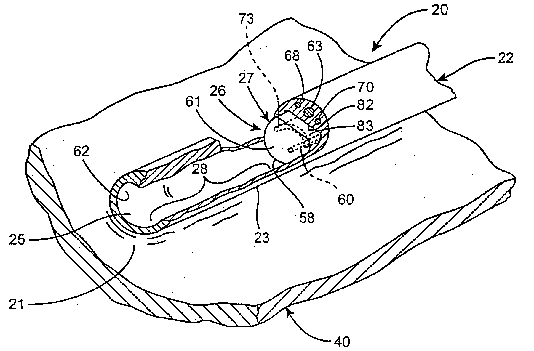
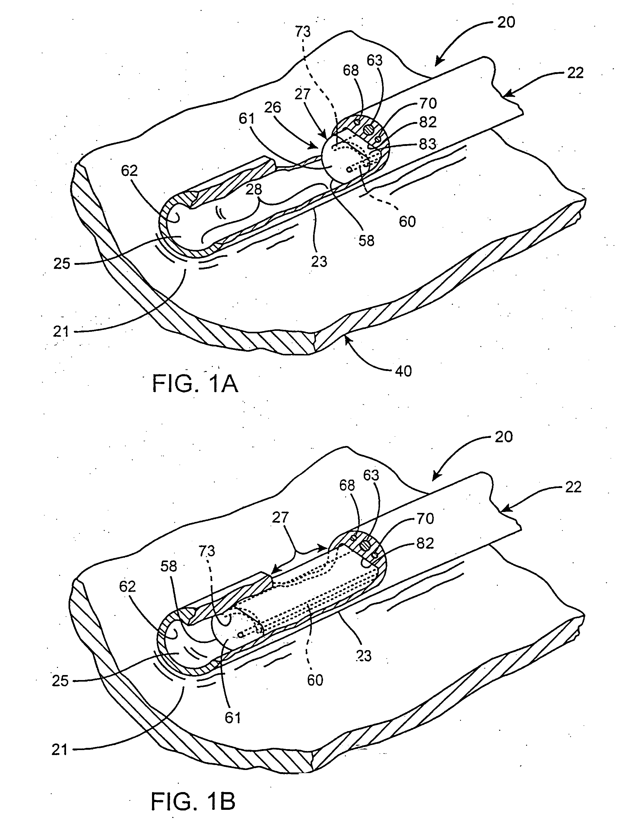
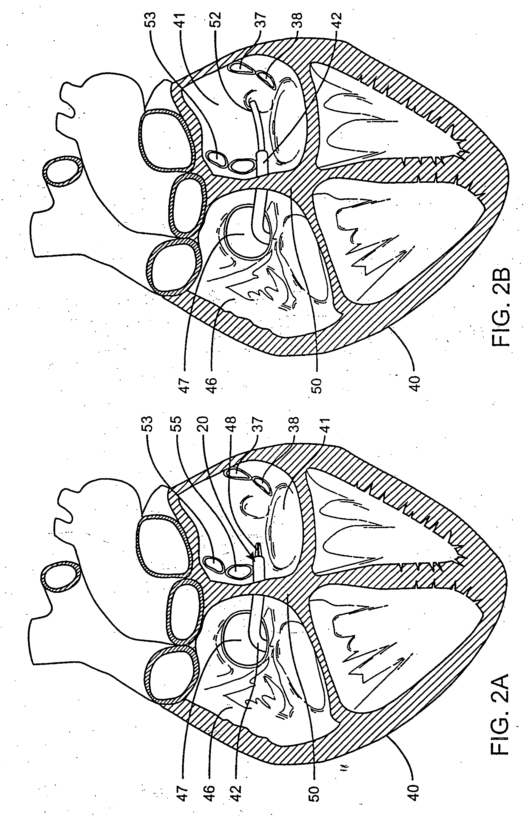
[0059] Turning generally now to FIGS. 1A-2D, an ablation system, generally designated 20, is provided for transmurally ablating a targeted tissue 21 of biological tissue. The system 20 is particularly suitable to ablate the epicardial or endocardial tissue 40 of the heart, and more particularly, to treat medically refractory atrial fibrillation of the Heart. The ablation system 20 for ablating tissue within a body of a patient in...


PUM


Abstract

A system and method for positioning a medical instrument at a desired biological target tissue site is provided. The system includes an elongated sheath having a deflectable distal end configured to deflect or otherwise position at least a portion of a medical instrument during a surgical procedure allowing for the placement of the deflected portion adjacent or proximate to a predetermined target tissue surface. The positioning system may be incorporated into the medical instrument. The medical instrument may be an ablation system.

Description

[0001] This application is a Continuation-in-Part of U.S. patent application Ser. No. 09 / 751,472, filed Dec. 29, 2000, which is incorporated herein by reference; in its entirety.BACKGROUND OF THE INVENTION [0002] 1. Field of Invention [0003] The present invention relates, generally, to ablation instrument systems that use ablative energy to ablate internal bodily tissues. More particularly, to preformed guide apparatus which cooperate with energy delivery arrangements to direct the ablative energy in selected directions along the guide apparatus. [0004] 2. Description of the Prior Art [0005] It is well documented that atrial fibrillation, either alone or as a consequence of other cardiac disease, continues to persist as the most common cardiac arrhythmia. According to recent estimates, more than two million people in the U.S. suffer from this common arrhythmia, roughly 0.15% to 1.0% of the population. Moreover, the prevalence of this cardiac disease increases with age, affecting nea...

Claims


Application Information

Patent Timeline
Patent Type & Authority Applications(United States)
IPC IPC(8): A61B18/18A61B1/00A61B17/00A61B18/20A61B18/00A61B18/12A61B18/14A61F7/10A61M25/00A61N1/06A61N5/04
CPCA61B18/1492A61B18/18A61B18/1815A61B2017/00243A61B2018/00375A61B2018/00839A61B2018/1407A61B18/02A61B2018/0212A61B2018/1497
Inventor CHIN, SING FATTBERUBE, DANYMODY, DINESH I.NORRIS, NANCY
Owner MAQUET CARDIOVASCULAR LLC
Why Eureka
Try Eureka