Burner assembly for particulate trap regeneration

a technology of particulate traps and burners, which is applied in the direction of mechanical equipment, machines/engines, light and heating equipment, etc., can solve the problems of patents not being configured, filter and/or engine performance to decline, etc., and achieve the effect of increasing the temperature of the particulate trap

Inactive Publication Date: 2006-10-05
SOLAR TURBINES
View PDF26 Cites 79 Cited by
  • Summary
  • Abstract
  • Description
  • Claims
  • Application Information

AI Technical Summary

Benefits of technology

[0011] In another aspect, the present disclosure is directed toward a method of regenerating an exhaust particulate trap. The method may include directing an exhaust flow, produced by an engine, into a burner assembly, the exhaust flow including at least a portion of a totality of exhaust gases produced by an engine, the burner assembly being located upstream from a particulate trap configured to remove one or more types of particulate matter from the exhaust flow. The method may further include directing the exhaust flow through an exhaust flow distribution member and thereby substantially evenly distributing the exhaust flow about a combustion chamber member to remove heat from the combustion chamber member, the heat being created by a flame within the combustion chamber member. The method may also include heating the exhaust flow in stages as the exhaust flow passes through the burner assembly by exposing a portion of the exhaust flow to the flame at a first stage and exposing additional portions of the exhaust flow to the flame at each subsequent stage to create a heated exhaust flow. In addition, the method may include directing the heated exhaust flow out of the burner assembly and to the particulate trap to thereby increase a temperature of the particulate trap.

Problems solved by technology

The use of the particulate trap for extended periods of time, however, may enable particulate matter to accumulate on the filter, thereby causing the functionality of the filter and / or engine performance to decline.
Further, the system of the '524 patent is not configured to impart rotational motion on fresh air introduced to a fuel injector of the burner to promote an even distribution of the burner flame.

Method used


Image

  • Burner assembly for particulate trap regeneration
  • Burner assembly for particulate trap regeneration
  • Burner assembly for particulate trap regeneration

Examples


Embodiment Construction

[0016] Reference will now be made in detail to the drawings. Wherever possible, the same reference numbers will be used throughout the drawings to refer to the same or like parts.

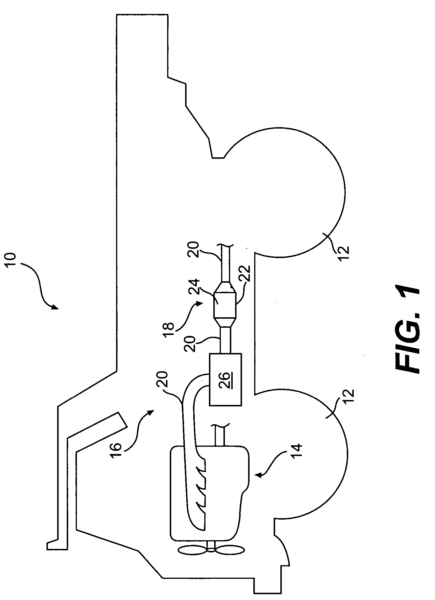
[0017]FIG. 1 illustrates a work machine 10. Work machine 10 may include one or more traction devices 12, an engine 14, and an exhaust treatment system 16.

[0018] Although work machine 10 is shown as a truck, work machine 10 could be any type of machine having an exhaust producing engine. Accordingly, traction devices 12 may be any type of traction devices, such as, for example, wheels, as shown in FIG. 1, tracks, belts, or any combinations thereof.

[0019] Engine 14 may be any kind of engine that produces an exhaust flow of exhaust gases. For example, engine 14 may be an internal combustion engine, such as a gasoline engine, a diesel engine, a natural gas engine or any other exhaust gas producing engine.

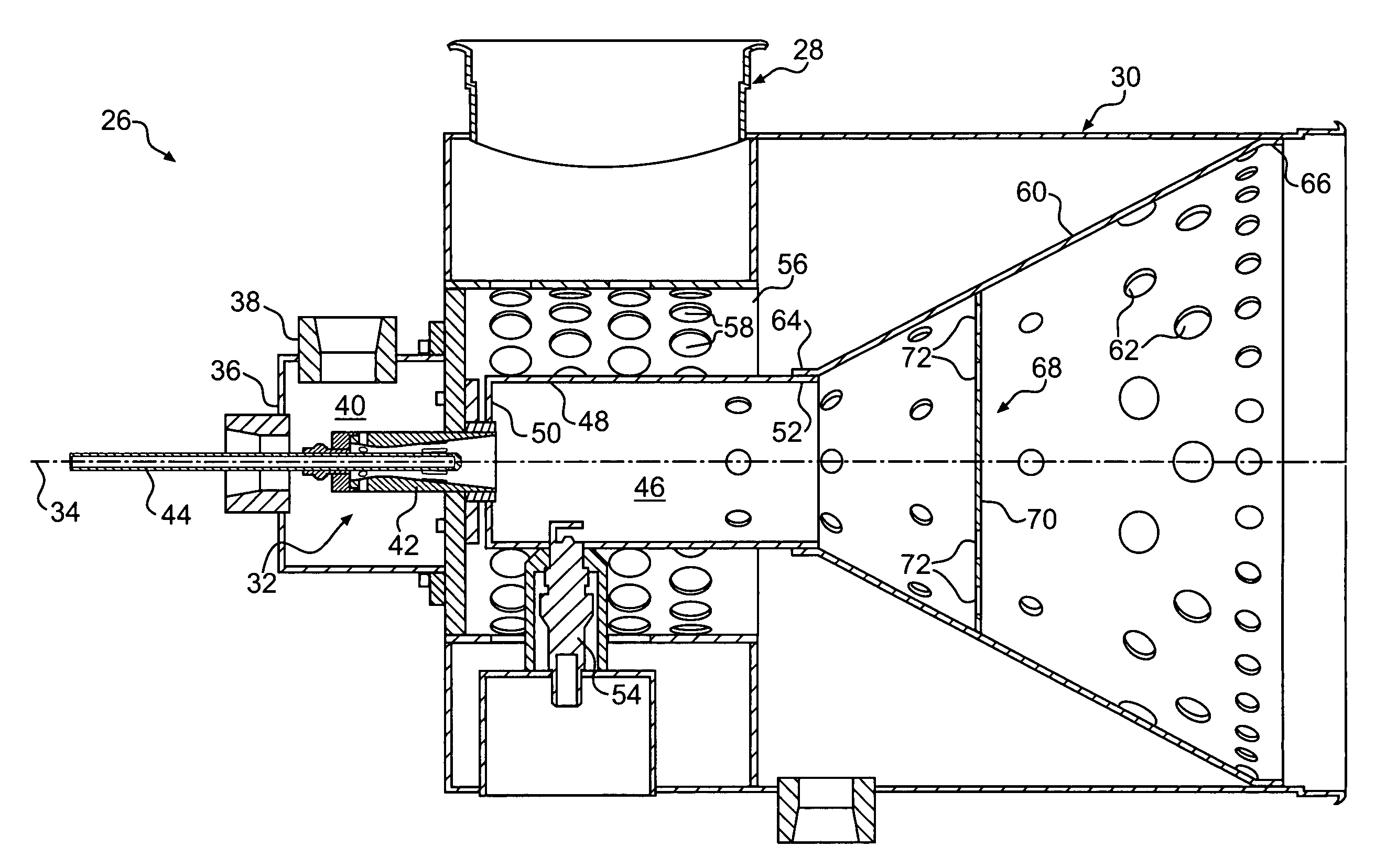
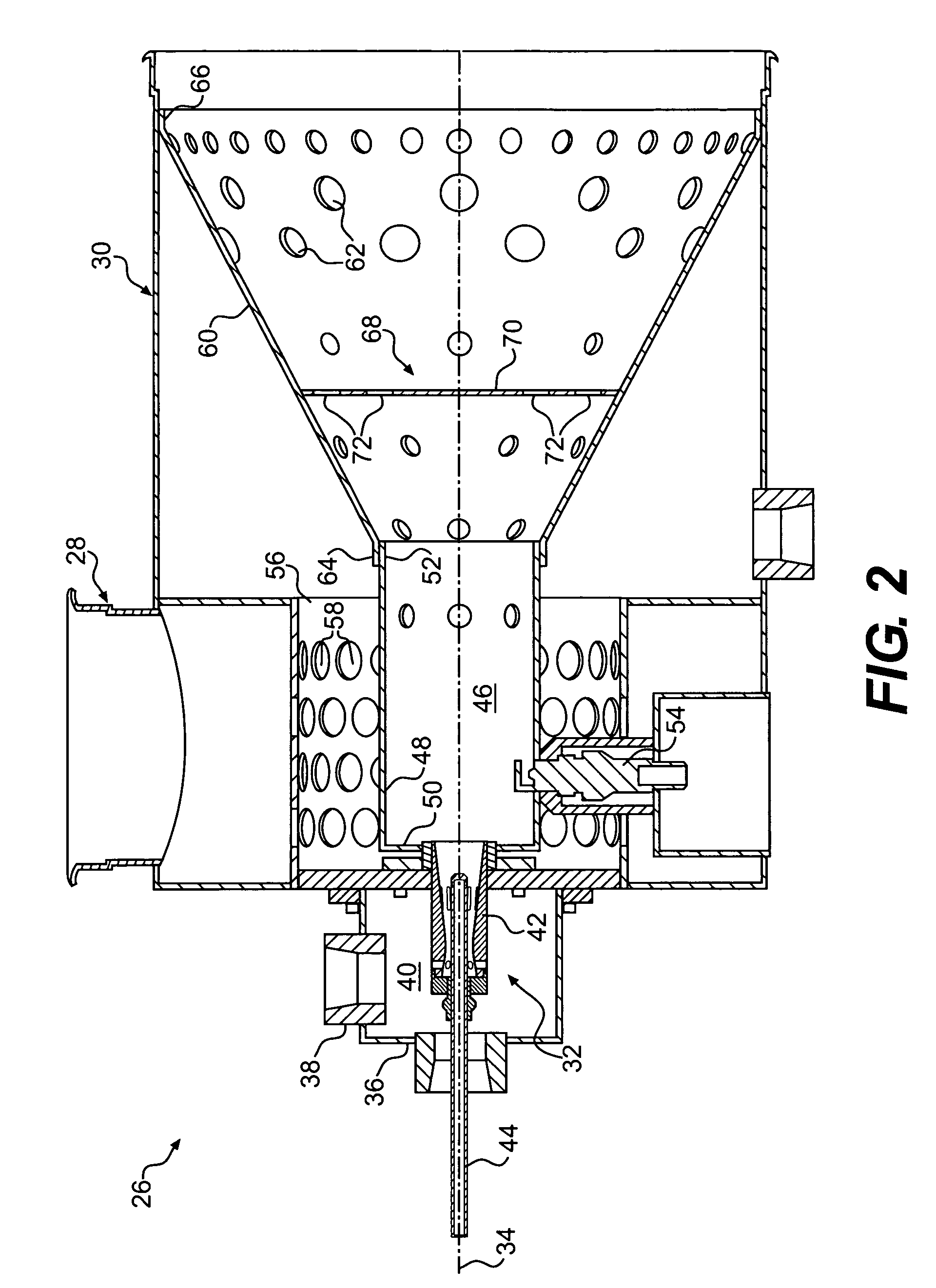
[0020] System 16 may include a particulate trap 18 and an exhaust conduit 20 for directing all or a port...


PUM


Abstract

An exhaust treatment system is provided. The system may include a particulate trap configured to remove one or more types of particulate matter from an exhaust flow, the exhaust flow including at least a portion of a totality of exhaust gases produced by an engine. The system may further include a burner assembly configured to increase a temperature of gases in the exhaust flow at a location upstream from the particulate trap. The burner assembly may include an exhaust inlet oriented in a direction along a first axis and configured to direct the exhaust flow into the burner assembly and an exhaust outlet oriented in a direction along a second axis at an angle relative to the first axis, the exhaust outlet being configured to direct the exhaust flow out of the burner assembly toward the particulate trap. The burner assembly may also include a fuel injector having a longitudinal axis in substantial alignment with the second axis. In addition, the burner assembly may include a cylindrical combustion chamber member defining a combustion chamber, having a longitudinal axis in substantial alignment with the longitudinal axis of the fuel injector, and configured to house a flame that is fueled by the fuel injector within the combustion chamber. The burner assembly may further include an exhaust flow distribution member configured to substantially evenly distribute exhaust about the combustion chamber member and in a heat exchange relation to the combustion chamber member.

Description

TECHNICAL FIELD [0001] The present disclosure is directed to a particulate trap regeneration system and, more particularly, to a particulate trap regeneration system having a burner assembly configured to increase the temperature of exhaust gases directed to the particulate trap. BACKGROUND [0002] Engines, including diesel engines, gasoline engines, natural gas engines, and other engines known in the art, may exhaust a complex mixture of air pollutants. The air pollutants may be composed of both gaseous and solid material, such as, for example, particulate matter. Particulate matter may include ash and unburned carbon particles called soot. [0003] Due to increased environmental concerns, exhaust emission standards have become more stringent. The amount of particulates and gaseous pollutants emitted from an engine may be regulated depending on the type, size, and / or class of engine. In order to meet these emissions standards, engine manufacturers have pursued improvements in several ...

Claims


Application Information

Patent Timeline
Patent Type & Authority Applications(United States)
IPC IPC(8): F01N3/00F01N13/08
CPCF01N3/025F01N13/08F01N2240/02F01N2240/14F23D2900/21003F01N2470/04F01N2470/18F23D11/103F23D99/003F01N2260/04F23D91/02
Inventor ARELLANO, LEONELPHI, VUFAHME, ANTHONYKUBASCO, ALANSMITH, KENNETH
Owner SOLAR TURBINES
Why Eureka
Try Eureka