Self-triggering superconducting fault current limiter

a fault current limiter and superconducting technology, applied in the direction of emergency protective circuit arrangements, emergency protective arrangements for limiting excess voltage/current, electrical equipment, etc., to achieve the effect of significant flexibility and fast quenching

Inactive Publication Date: 2006-10-05
SUPERPOWER INC
View PDF15 Cites 11 Cited by
  • Summary
  • Abstract
  • Description
  • Claims
  • Application Information

AI Technical Summary

Benefits of technology

[0008] It is an objective of this invention to provide a passive scalable MFCL design that achieves fast quenching using magnetic field as a main trigger mechanism and a shunt inpedance to provide a significant degree of flexibility in achieving current limiting purposes of the MFCL, both the trigger mechanism and the shunt impedance are electrically connected in parallel with a superconducting element.
[0009] Briefly, in accordance with one embodiment of the present invention, a superconducting fault current limiter is provided which has at least one HTS element coupled in parallel with an inductive component and also coupled in parallel with a shunt. The inductive component, herein referred to as trigger coil, is electrically connected in parallel with a superconductive element and a shunt element to form the base structure of the fault current limiter. The trigger coil is physically disposed around the HTS in such a way so that the magnetic field generated by the current in the trigger coil will be uniformly applied to the HTS. Under normal operating condition, the superconducting element will have no resistance and thus all current will flow through it. Consequently, there is no voltage drop across the whole arrangement and the parallel connected shunt and trigger coil will have no current flowing through them. Once there is a fault however, the current surge will exceed the critical current level of the superconductor element and cause it to quench immediately, thus generating a sufficiently large voltage drop across the shunt and trigger coil which results in part of the overall current being diverted into the shunt and trigger coils. The resulting current in the trigger coil will generate a magnetic field that is uniformly applied to the superconductor which acts to further quench the superconductor uniformly. The shunt will act to limit the voltage generated by the superconductor and share the total currnet to insure that the superconductor does not overheat and can quickly return to its normal state once the fault has been removed.

Problems solved by technology

Once there is a fault however, the current surge will exceed the critical current level of the superconductor element and cause it to quench immediately, thus generating a sufficiently large voltage drop across the shunt and trigger coil which results in part of the overall current being diverted into the shunt and trigger coils.

Method used


Image

  • Self-triggering superconducting fault current limiter
  • Self-triggering superconducting fault current limiter
  • Self-triggering superconducting fault current limiter

Examples


Embodiment Construction

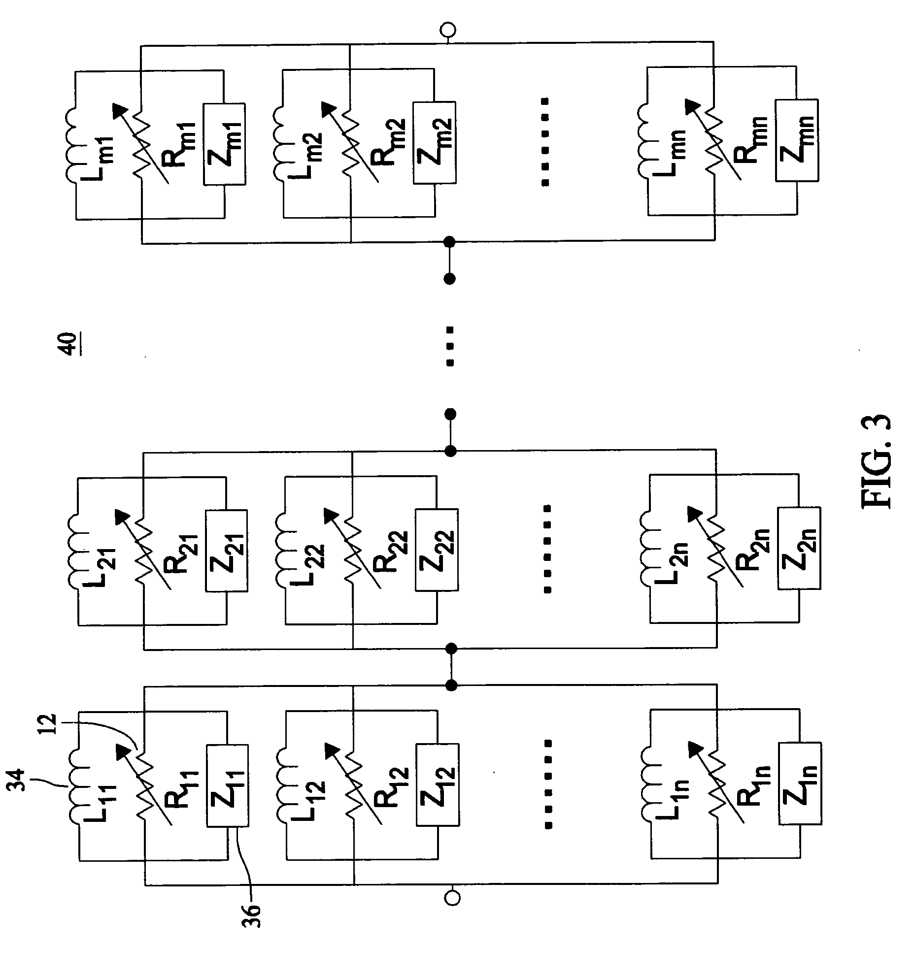
[0020] U.S. patent application Ser. No. 10 / 877,838, entitled “Superconducting Matrix Fault Current Limiter With Current-Driven Trigger Mechanism”, filed on Jun. 25, 2004, assigned to the assignee of the present invention, which is a Continuation-In-Part of U.S. patent application Ser. No. 10 / 609969, filed on Jun. 30, 2003, are both herein incorporated by reference in their entirety. These applications describe MFCL designs which are modular and scalable that functions as a “variable impedance” using components made of superconducting as well as conventional electrically conductive materials.

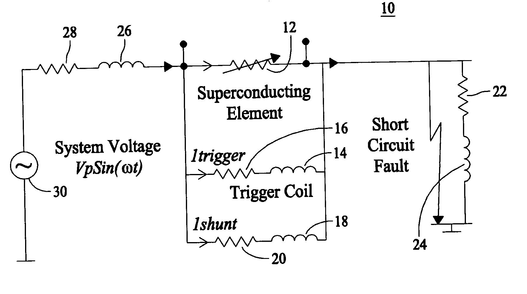
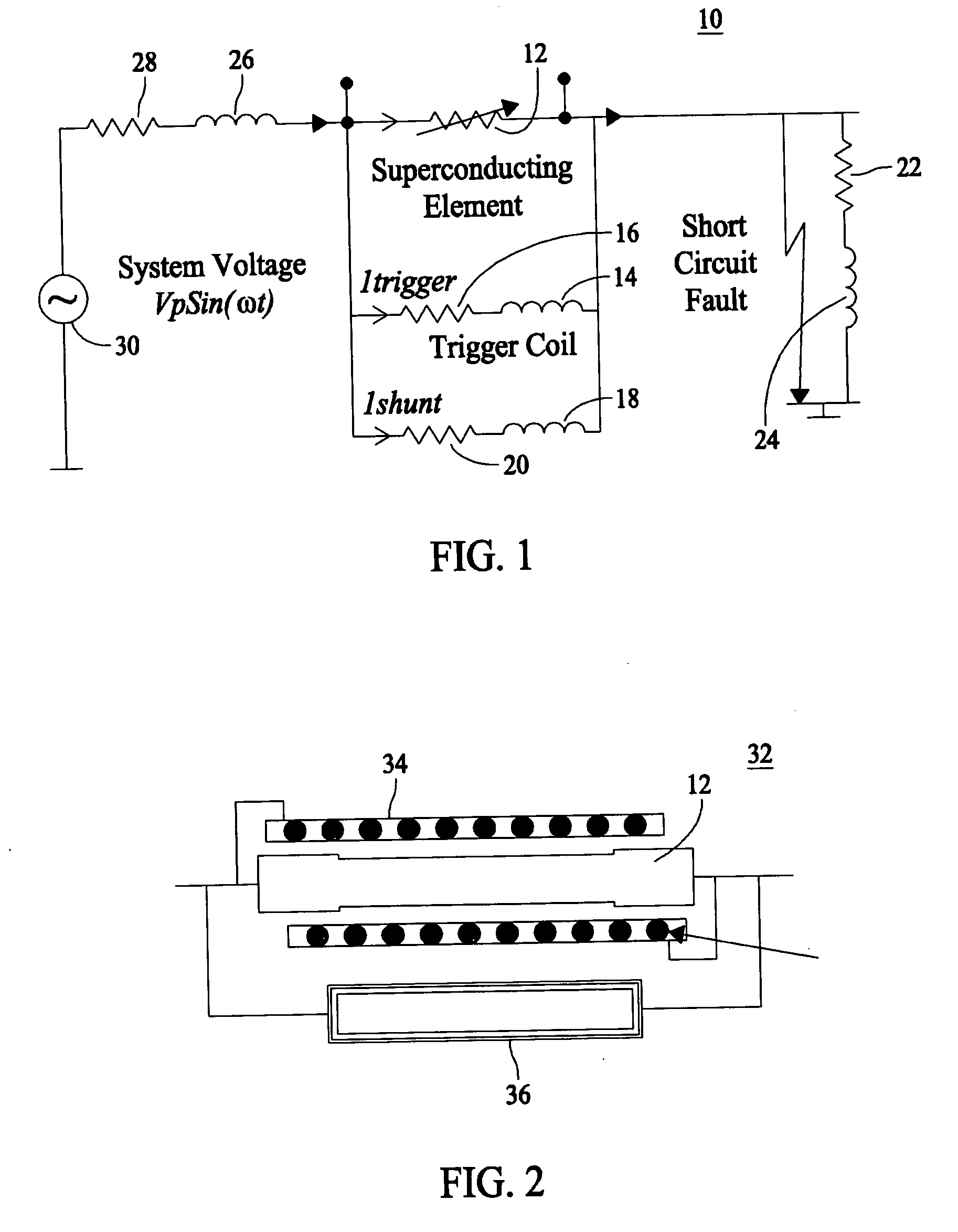
[0021]FIG. 1 is a simplified schematic single phase line diagram of a three-phased alternating current (AC) electrical power system 10 of the present invention under a short circuit fault condition. This diagram illustrates the system power source 30, line resistance 28, line inductance 26, and load impedance which usually comprises a resistance 22 and / or an inductance 24. In series with system ...


PUM


Abstract

A modular and scaleable Matrix Fault Current Limiter (MFCL) that functions as a “variable impedance” device in an electric power network, using components made of superconducting and non-superconducting electrically conductive materials. The matrix fault current limiter comprises a fault current limiter module that includes a superconductor which is electrically coupled in parallel with a trigger coil, wherein the trigger coil is magnetically coupled to the superconductor. The current surge doing a fault within the electrical power network will cause the superconductor to transition to its resistive state and also generate a uniform magnetic field in the trigger coil and simultaneously limit the voltage developed across the superconductor. This results in fast and uniform quenching of the superconductors, significantly reduces the burnout risk associated with non-uniformity often exitsting within the volume of superconductor materials. The fault current limiter modules may be electrically coupled together to form various “n” (rows)דm” (columns) matrix configurations.

Description

[0001] The U.S. government has a paid-up license in this invention and the right in limited circumstances to require to the patent owner to license others on reasonable terms as provided for in the terms of Contract No. DE-FC36-03G013033 awarded by the Department of Energy.BACKGROUND [0002] The invention relates generally to a current limiter and more specifically to a superconducting fault current limiter. [0003] Current limiting devices are critical in electric power transmission and distribution systems. For various reasons such as lightening strikes, short circuit conditions can develop in various sections of a power grid causing sharp surge in current. If this surge of current, which is often referred to as fault current, exceeds the protective capabilities of the switchgear equipment deployed throughout the grid system, it could cause catastrophic damage to the grid equipment and customer loads that are connected to the system. [0004] Superconductors, especially high-temperatu...

Claims


Application Information

Patent Timeline
Patent Type & Authority Applications(United States)
IPC IPC(8): H02H7/00
CPCY02E40/68H02H7/001H02H9/023Y02E40/60
Inventor YUAN, XINGTEKLETSADIK, KASEGN
Owner SUPERPOWER INC
Why Eureka
Try Eureka