Catalyst-supporting fiber structure and method for producing same

a technology of supporting fiber and catalyst, which is applied in the direction of catalyst activation/preparation, organic compound/hydride/coordination complex catalyst, physical/chemical process catalyst, etc., can solve the problems of poor treatment efficiency, small amount of catalyst to be used, and complex operations, etc., to achieve the effect of reducing the number of harmful chemicals, simple method, and flexible catalyst support performan

Inactive Publication Date: 2006-10-05
TEIJIN LTD
View PDF3 Cites 26 Cited by
  • Summary
  • Abstract
  • Description
  • Claims
  • Application Information

AI Technical Summary

Benefits of technology

[0012] A primary object of the invention is to overcome the problems involved in the foregoing conventional technologies and to provide a fiber structure having both thorough flexibility and catalyst s...

Problems solved by technology

However, this method involved such a problem that since the amount of supporting the microorganisms is limited, the treatment efficiency is poor.
Thus, there were encountered problems that the operations are complicated and that the amount of the catalyst to be used is small.
However, there was also encoun...

Method used


Image

  • Catalyst-supporting fiber structure and method for producing same
  • Catalyst-supporting fiber structure and method for producing same
  • Catalyst-supporting fiber structure and method for producing same

Examples


example 1

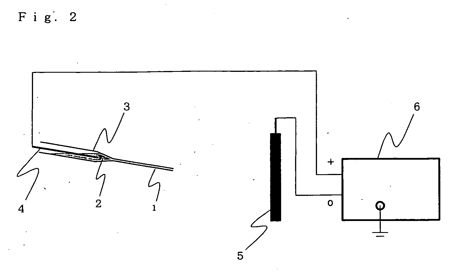
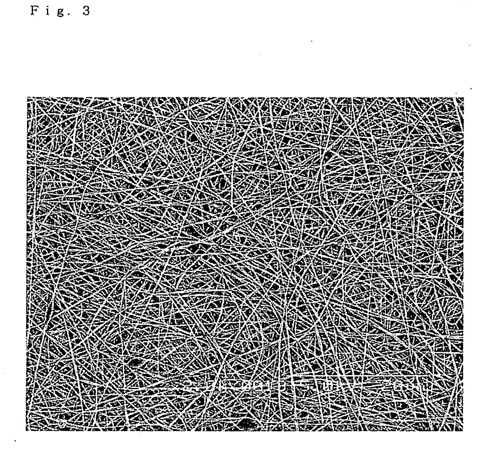
[0097] A solution consisting of 1 part by weight of polyacrylonitrile (manufactured by Wako Pure Chemical Industries, Ltd.) and 9 parts by weight of N,N-dimethylformamide (a reagent special grade, manufactured by Wako Pure Chemical Industries, Ltd.) was prepared. By using a device as shown in FIG. 2, the subject solution was discharged into a fibrous substance collecting electrode (5 in FIG. 2) for 30 minutes. An inner diameter of an injection nozzle (1 in FIG. 2) was 0.8 mm, a voltage was 12 kv, and a distance from the injection nozzle (1 in FIG. 2) to the fibrous substance collecting electrode (5 in FIG. 2) was 10 cm. The resulting fiber structure had a basis weight of 3 g / m2. The resulting fiber structure was observed by a scanning electron microscope (S-2400, manufactured by Hitachi, Ltd.) and found to have an average fiber diameter of 0.2 μm. A fiber having a fiber length of not more than 20 μm was not observed. Scanning electron microscope photographs of the resulting fiber st...

example 2

[0099] The same operations as in Example 1 were followed, except that after forming a fiber structure, the fiber structure was thermally treated at 300° C. for 3 hours.

[0100] The fiber structure as obtained after the thermal treatment was observed by a scanning electron microscope (S-2400, manufactured by Hitachi, Ltd.) and found to have an average fiber diameter of 0.2 μm. A fiber having a fiber length of not more than 20 μm was not observed. Scanning electron microscope photographs of the resulting fiber structure are shown in FIG. 6 and FIG. 7.

[0101] The resulting fiber structure was subjected to the same operations as in Example 1 to obtain a catalyst-supporting fiber structure. The ultimately obtained results of catalytic activity evaluation are shown in Table 1.

example 3

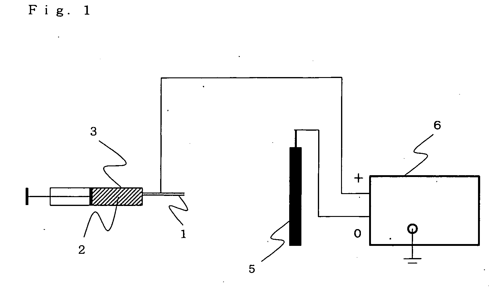
[0105] A solution consisting of 1 part by weight of poly(vinyl chloride) having a degree of polymerization of 1,300, 4.5 parts by weight of N,N-dimethylformamide (a special grade, manufactured by Wako Pure Chemical Industries, Ltd.), and 4.5 parts by weight of tetrahydrofuran (a special grade, manufactured by Wako Pure Chemical Industries, Ltd.) was prepared. Subsequently, by using a device as shown in FIG. 1, the subject solution was discharged into a fibrous substance collecting electrode (5 in FIG. 1) for 60 minutes. An inner diameter of an injection nozzle (1 in FIG. 1) was 0.8 mm, a solution feed rate was 20 μL / min, a voltage was 12 kV, and a distance from the injection nozzle (1 in FIG. 1) to the fibrous substance collecting electrode (5 in FIG. 1) was 20 cm. The resulting fiber structure was a non-woven fabric having a basis weight of 36 g / m2 and a thickness of 0.2 mm. The resulting fiber structure was observed by a scanning electron microscope (S-2400, manufactured by Hitach...


PUM

PropertyMeasurementUnit
Diameteraaaaaaaaaa
Diameteraaaaaaaaaa
Particle sizeaaaaaaaaaa

Abstract

A catalyst-supporting fiber structure having a catalyst supported on a fiber constituting a fiber structure having both thorough flexibility and catalyst supporting performance, wherein the fiber has an average fiber diameter of not more than 1 μm, and a fiber having a fiber length of not more than 20 μm is not substantially contained. Since the subject fiber structure is excellent in catalyst-supporting characteristic, for example, it is possible to provide a fiber structure having an extremely high ability to degrade harmful chemicals.

Description

TECHNICAL FIELD [0001] The present invention relates to a catalyst-supporting fiber structure having a catalyst supported on a fiber constituting a fiber structure and a production process of the same. BACKGROUND ART [0002] Because of destruction of the recent global environment, an environmental issue is taken up as a social problem and is getting increasingly popular more and more. Because, the environmental issue becomes intensified, development of high-degree removal technologies of harmful chemical pollutants is demanded. Above all, with respect to VOC (volatile organic chemical) such as benzene and trichloroethylene and endocrine-disrupting chemicals such as phthalic esters, serious influences against the human body entertain misgivings. In particular, with respect to the wastewater containing such chemicals, not only installment of large-scale treatment facilities but also substantially complete removal at individual sources of an outbreak begins to be demanded. [0003] As a m...

Claims


Application Information

Patent Timeline
IPC IPC(8): B01J31/00B01J35/02B01J35/06D01D5/00D01D5/04D01F6/92D04H1/728D06M11/46
CPCB01J31/06B01J35/004B01J35/06D06M11/46D01D5/0038D01F1/10B01J37/0215B01J35/02D01F6/92
Inventor MIYOSHI, TAKANORIKOMURA, SHINYAMINEMATSU, HIROYOSHINONOKAWA, RYUJI
Owner TEIJIN LTD
Why Eureka
Try Eureka