Differential with guided feedback control for rotary opposed-piston engine

a technology of opposed pistons and differential control, which is applied in the direction of liquid fuel engines, rotary piston liquid engines, machines/engines, etc., can solve the problems of inconvenient operation of rotary engines, inability to maintain constant power output of crankshafts, and current internal combustion engines that require complicated valving mechanisms, etc., to achieve greater cylinder pressure, greater efficiencies, and greater cylinder pressure

Active Publication Date: 2006-10-12
MCCOIN DAN K +1
View PDF30 Cites 16 Cited by
  • Summary
  • Abstract
  • Description
  • Claims
  • Application Information

AI Technical Summary

Benefits of technology

[0019] The rotary engine may be, for example, a pneumatic motor, a spark ignited engine, or a diesel cycle engine. The rotary engine may also be a heat engine such as, for example, a steam engine. In one embodiment, the rotary engine can be configured to perform a constant volume combustion cycle for at least a portion of the combustion event, allowing the engine to achieve greater efficiencies through higher cylinder pressures than conventional engines. Also, the engine can be configured to operate on a hyper-expansion cycle, allowing the engine to achieve greater efficiencies than in conventional engines. The rotary engine may be configured with scalloped pistons to make the combustion chambers of the engine more favorable for combustion. The engine may also be configured to start without an external starting device through manipulation of the hyper-expansion capability.

Problems solved by technology

Furthermore, the power output on the crankshaft is not constant.
Current internal combustion engines further require complicated valving mechanisms in order to introduce fuel and air into the cylinder and to release exhaust gases.
What is currently lacking in the art is a practical rotary engine.
Prior attempts have not been commercially viable and do not overcome critical challenges.
The primary obstacle to achieving a practical rotary engine lies in the shape of the chamber itself.
Defining a fixed barrier is problematic because the piston must constantly change direction once it reaches the barrier.
Prior systems provide no adequate means to control the pistons providing a smooth output at high output torques.
However, such systems simply obstruct the motion of the piston.
Accordingly, at high angular velocities the piston will repeatedly strike the stopping mechanism at high speeds causing premature breakage.
Prior designs also provide no blending of motion to give a smooth output torque.
Motion of the piston in prior systems is simply rectified to the correct rotational direction but is not controlled to provide a smooth angular velocity output.
In addition to providing a low quality output, such systems are subject to a great deal of mechanical shock, clatter, wear, and breakage, regardless of load, resulting in a very short useful life.

Method used


Image

  • Differential with guided feedback control for rotary opposed-piston engine
  • Differential with guided feedback control for rotary opposed-piston engine
  • Differential with guided feedback control for rotary opposed-piston engine

Examples


Embodiment Construction

[0043] Reference throughout this specification to “one embodiment,”“an embodiment,” or similar language means that a particular feature, structure, or characteristic described in connection with the embodiment is included in at least one embodiment of the present invention. Thus, appearances of the phrases “in one embodiment,”“in an embodiment,” and similar language throughout this specification may, but do not necessarily, all refer to the same embodiment.

[0044] Furthermore, the described features, advantages, and characteristics of the invention may be combined in any suitable manner in one or more embodiments. One skilled in the relevant art will recognize that the invention can be practiced without one or more of the specific features or advantages of a particular embodiment. In other instances, additional features and advantages may be recognized in certain embodiments that may not be present in all embodiments of the invention.

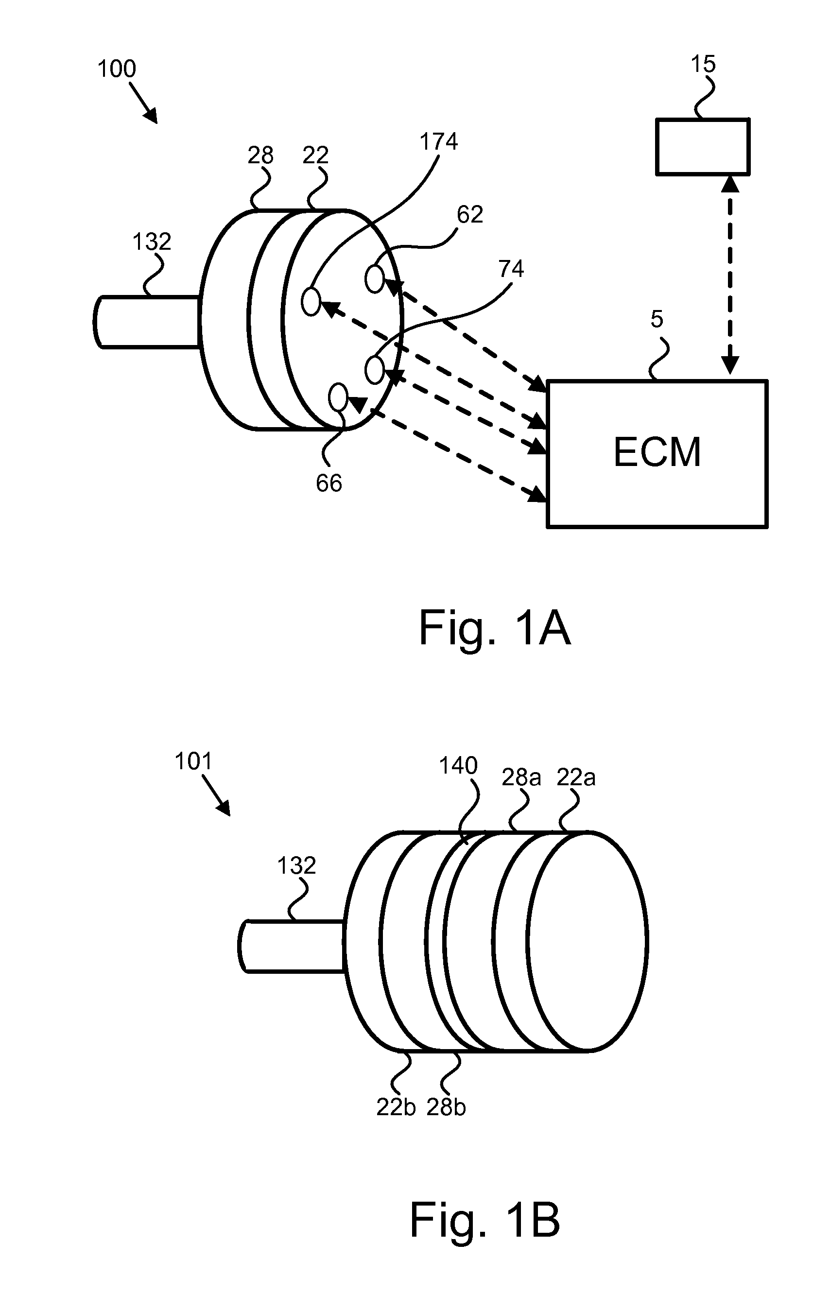
[0045]FIG. 1 illustrates one embodiment of a sys...


PUM


Abstract

A gear set is disclosed having a guide, such as a cam, engaging the output shaft of the gear shaft and being indexed thereby. The guide drives one or more followers which in turn drive one or more interfaces of a differential gear set. The output shaft may be driven by a third interface of the differential gear set. The followers may likewise engage piston assemblies in order to control the piston assemblies during execution of a process such as a four stroke combustion process, or other process involving compression or expansion of a gas. The piston assemblies are enclosed within a housing defining an annular chamber, such as a toroid. Apertures formed in the housing allow exhaust gases to leave and air to be taken in. In one embodiment, a hyper expansion port is formed in the housing to release a portion of the air during the compression stroke in order to decrease the pressure of combustion gases.

Description

CROSS-REFERENCES TO RELATED APPLICATIONS [0001] This application claims the benefit of U.S. Provisional Patent Application No. 60 / 670,567 entitled “DIFFERENTIAL WITH GUIDED FEEDBACK CONTROL FOR ROTARY OPPOSED-PISTON ENGINE” and filed on Apr. 12, 2005 for Dan K. McCoin and Mark D. McCoin, which is incorporated herein by reference.BACKGROUND OF THE INVENTION [0002] 1. Field of the Invention [0003] This invention relates generally to rotary engines and more particularly to rotary opposed-piston engines. [0004] 2. Description of the Related Art [0005] The vast majority of internal combustion engines currently in use are reciprocating engines in which a piston moves up and down within a cylinder. The linear motion of the piston is translated into rotary motion by a crankshaft connected to the piston by a piston rod. In a typical engine, due to the large forces involved, the coupling between the crankshaft and the piston rod and between the piston and the piston rod, is a simple journal b...

Claims


Application Information

Patent Timeline
Patent Type & Authority Applications(United States)
IPC IPC(8): F02B53/00
CPCF01C1/067
Inventor MCCOIN, DAN K.MCCOIN, MARK D.
Owner MCCOIN DAN K
Why Eureka
Try Eureka