Vent and relief valve

Inactive Publication Date: 2006-10-12
CIRCLE SEAL CONTROL
View PDF11 Cites 7 Cited by
  • Summary
  • Abstract
  • Description
  • Claims
  • Application Information

AI Technical Summary

Benefits of technology

[0010] An advantage of the present invention is that the dual stop guard provides a stop for both the relief valve and a stop for the vent valve.
[0011] Another advantage of the present invention is that the dual stop guard provides protection for the relief valve, particularly during installation. In particular, the embodiment of the invention including metallic bellows in the relief valve are protected from damage.
[0012] Still another advantage of the present invention is that the dual stop guard permits the valves to seat against each other and provide an improved seal, while still providing a stop for both the vent valve and the relief valve.
[0013] Still another advantage of the present invention is that the multiple outlet provides smaller outlet ducts from the valve. Smaller outlet ducts permit the valve to have a reduced height, while maintaining relief and vent capacity. The reduced height reduces the space required for the valve and allows a greater amount of area for other components in an application such as a space launch vehicle.
[0014] Still another advantage of the present invention is that the multiple outlet ducts provides fluid relief resulting in reduced side or internal thrust. In one embodiment having a dual outlet duct, the thrust may be equalized in order to substantially prevent thrust in a single direction.
[0015] Still another advantage of the present invention is that the multiple outlet ducts provides an increased area of venting, allowing the recess of the actuator into the valve further reducing the height of the valve. The reduced height reduces the space required for the valve and allows a greater amount of area for other components for the launch vehicle.

Problems solved by technology

The non-coaxial flow path around the main flow element is tortuous and significantly impedes flow exhausting from the tank.
It also is possible that the main valve could jam or stick in the sliding bore of the body as a result of cyclic wear induced material galling, particulate contamination, thermal distortion or any combination thereof.
This single point failure would cause both the vent and relief operating modes to be degraded or totally inoperative, allowing the possibility of overpressurization and catastrophic failure of the tank.
The Reinicke patent valve has the drawback that the bellows of the relief valve are not protected from damage, particularly during installation into the tank.
Further, the Reinicke patent has independent and separate travel stops for the vent mode poppet and relief mode seat, making valve assembly and adjustment more tedious and providing for a less consistent and reliable operation under thermal transient conditions.
The Reinicke patent also has the drawback that it has a single outlet providing for a valve having a relatively large height from the top of the tank, taking up valuable space, for example, in a space launch vehicle.
The single outlet has the further disadvantage that a side thrust force is created during the vent and / or relief functions of the valve due to the fluid exhausting from the single outlet duct, and a special flow splitter with diametrically opposing outlets must be added to mitigate side thrust force.

Method used


Image

  • Vent and relief valve
  • Vent and relief valve
  • Vent and relief valve

Examples


Embodiment Construction

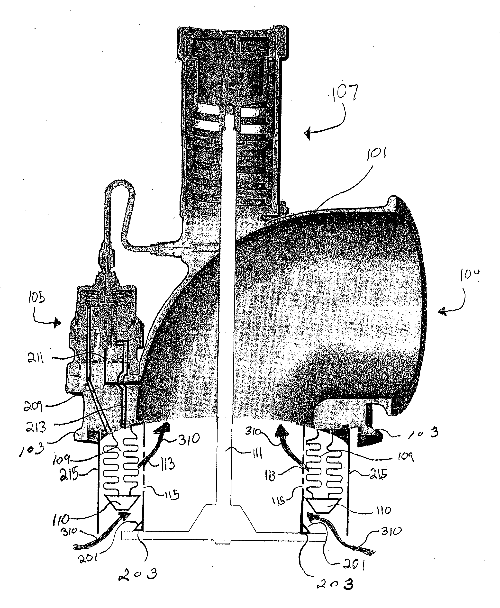
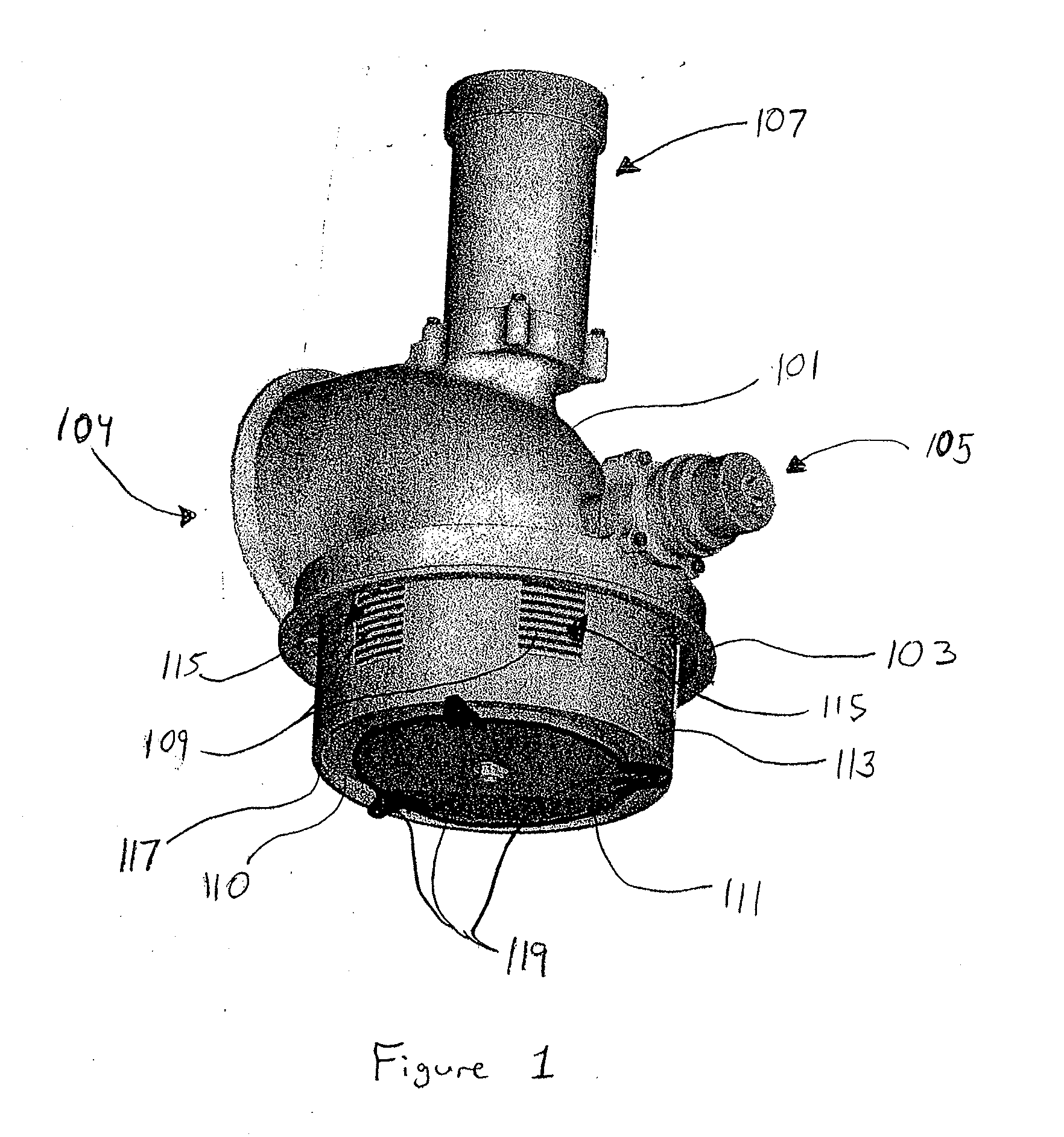
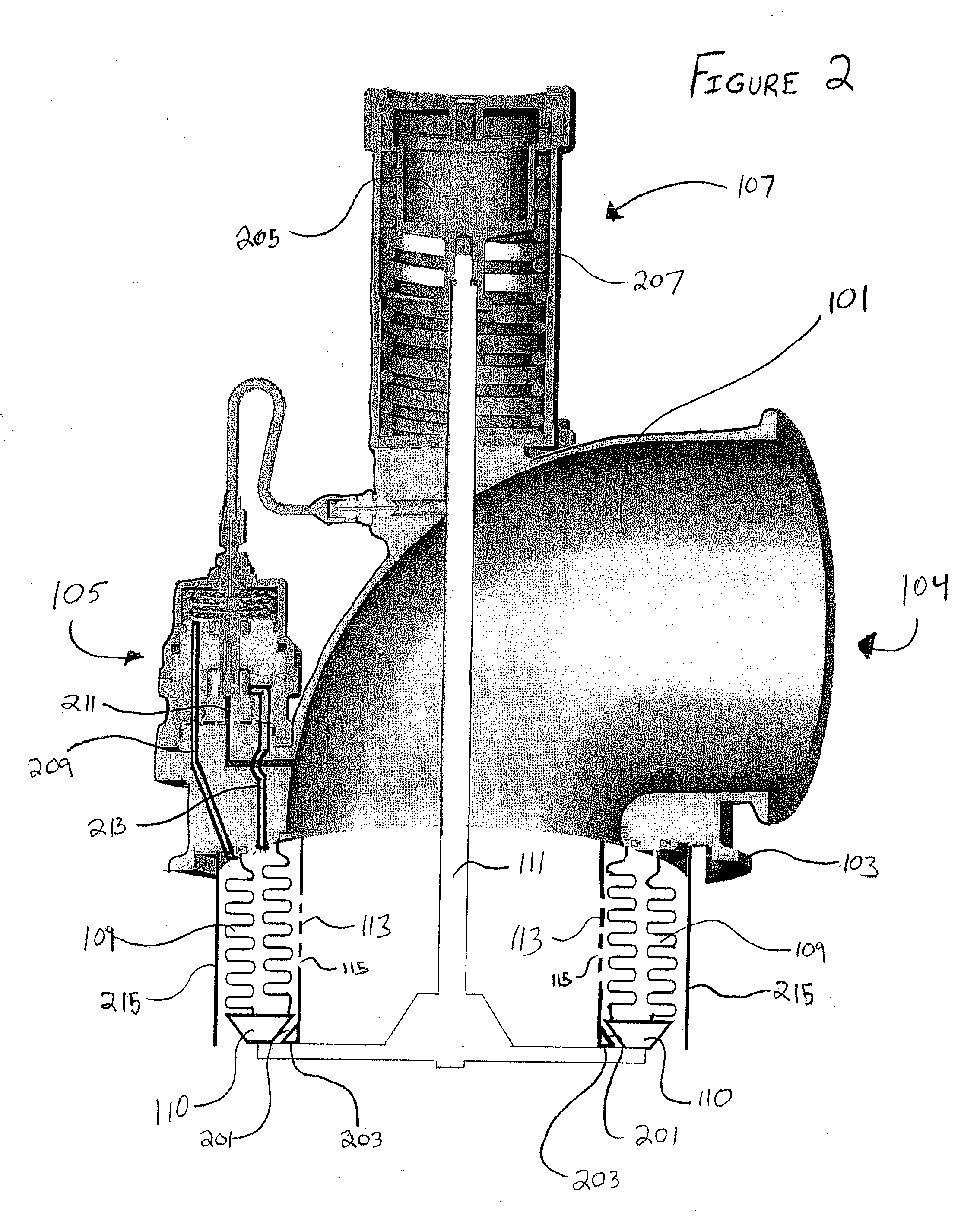
[0027]FIG. 1 shows a perspective view of a vent and relief valve according to an embodiment of the present invention. The vent and relief valve includes a valve body 101 which attaches to a tank (not shown) by attachment flange 103. The tank may contain a pressurized fluid, such as, for example, cryogenic liquefied oxygen, hydrogen, or hydrocarbon liquid, such as kerosene. The valve body 101 also includes a pilot valve 105 that operates a relief valve 109. The relief valve 109 is a bellows structure having a relief valve seat portion 110 that is capable of being drawn up into an open position to release fluid from the tank gas ullages. The valve body 101 further includes an actuator mechanism 107 that operates a vent valve 111. The vent valve 111 is a poppet valve that extends from the base of the valve which is adjacent to the fluid in the tank upward toward the valve body 101 into the actuator mechanism 107. A valve stop 113 is coaxial positioned coaxially with respect to the reli...


PUM


Abstract

A vent and relief valve having a valve body that is in fluid communication with the interior of a tank containing a fluid. A vent valve and relief valve are positioned within the valve body. The vent valve is capable of being configured into an open position to vent fluid from the interior of the tank. The relief valve is capable of being configured into an open position to relieve pressure within a tank. The relief valve is also capable of engaging the vent valve to form a seal to substantially prevent fluid from flowing from the tank. The valve body also includes a valve seat having a first surface that releasably engages the vent valve when the vent valve is in a closed position and a second surface that releasably engages the relief valve when the relief valve is in a closed position.

Description

FIELD OF THE INVENTION [0001] The present invention is directed to coaxial flow vent and relief valves for pressurized fluid tanks, ullages and ducts. In particular, the present invention is directed, but not limited to, vent and relief valves for use in cryogenic liquefied gases and hydrocarbon fuel space launch vehicle rocket propellant tank applications. BACKGROUND OF THE INVENTION [0002] Pressurized propellant tanks, including tanks for storage of cryogenic liquefied gases, such as oxygen and hydrogen, and liquid hydrocarbons, such as kerosene, generally include a vent opening at the top thereof. Vent and relief valves are typically mounted on the top of the tanks. Alternatively, the vent and relief valves are mounted in the discharge vents of the tanks. The vent and relief valves provide a vent function and a pressure relief function. The vent function includes the ability for the vent and relief valve to vent the tank, such as during the filling of the tank or when it is other...

Claims


Application Information

Patent Timeline
IPC IPC(8): F16K5/10
CPCF16K17/19F16K27/07F16K24/06F16K24/04Y10T137/8803
Inventor REINICKE, ROBERT H.SCHROEPFER, DAVID J.
Owner CIRCLE SEAL CONTROL
Why Eureka
Try Eureka