This helps you quickly interpret patents by identifying the three key elements:
Problems solved by technology
Method used
Benefits of technology
Benefits of technology
[0018] The present invention has been devised to solve the above conventional problems, it is therefore an object of the present invention to provide a fluorescence detecting apparatus which enables separation and detection of weak fluorescent spots emitted from an extremely trace amount of sample, in a 2-dimensional area and enables detection of the continuous changes of a process.
[0027] With the above configuration, it is possible to irradiate different intensities of excitation light optimal for individual places on the sample surface at almost the same time. That is, irradiation of weak excitation light on areas that contain large amounts of fluorescent dyes hence would emit strong fluorescence makes it possible to excite reduced amounts of fluorescence and thereby inhibit adverse effects such as blurring or spreading of light of fluorescent wavelengths around the areas as well as to prevent the high-sensitivity fluorescence detecting device from being saturated by excessive amounts of light. On the other hand, irradiation of strong excitation light on areas that contain lower amounts of fluorescent dyes hence would emit weak fluorescence makes it possible to obtain high enough amounts of fluorescence that can be detected by the fluorescence detecting device.
[0028] As described above, the apparatus of the present invention includes: a light source device for illuminating a sample with excitation light; a fluorescence detector for detecting fluorescence emitted from the sample; and an excitation light pattern generator disposed in the light path from the light source to the sample for generating a 2-dimensional illumination pattern of excitation light to be irradiated over the sample surface in accordance with the detected result from the fluorescence detector. It is therefore possible to irradiate different intensities of excitation light optimal for individual places on the sample surface at almost the same time.
[0029] Further, by illuminating areas that contain large amounts of fluorescent dyes hence would emit strong fluorescence, with weak excitation light it is possible to emit reduced amounts of fluorescence and thereby inhibit adverse effects such as blurring or spreading of light of fluorescent wavelengths around the areas as well as to prevent the high-sensitivity fluorescence detecting device from being saturated by excessive amounts of light. On the other hand, by illuminating areas that contain lower amounts of fluorescent dyes hence would emit weak fluorescence, with strong excitation light it is possible to obtain high enough amounts of fluorescence that can be detected by the fluorescence detecting device.
Problems solved by technology
However, in the aforementioned conventional fluorescence detecting apparatus configurations, it has been impossible for any of the apparatus configurations to accomplish both the purpose of detecting separation of an extremely trace amount of a sample and the purpose of detecting a continuous separation process of the sample at the same time.
However, it takes long time for detection because detection is performed basically one spot at a time and scanning needs to be performed over the entire 2-dimensional area.
Accordingly, it is practically impossible to perform a continuous process of separation except when separation and change of the sample is very slow.
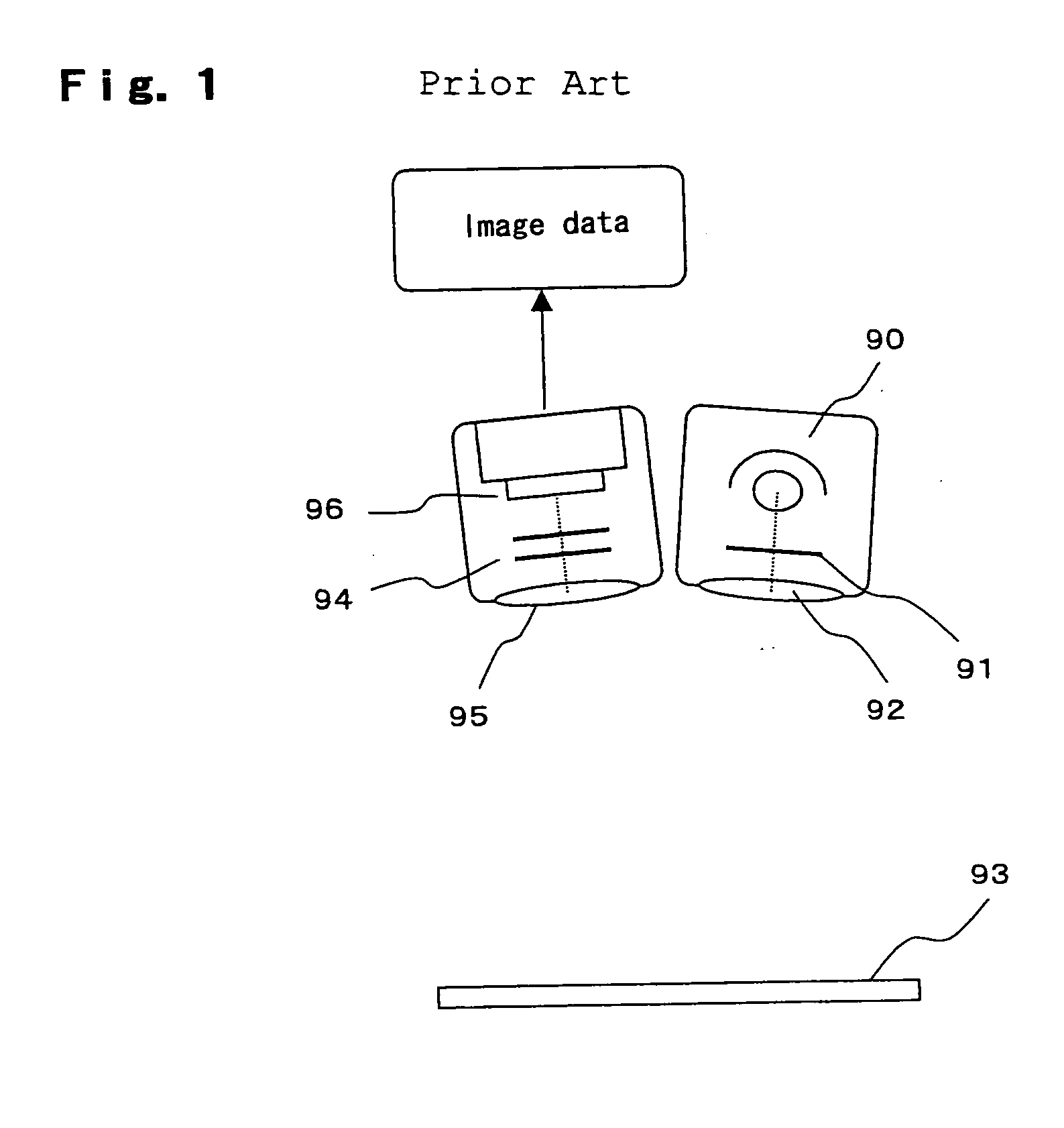
However, since in this configuration the image pickup area is illuminated as a whole by an area light source, it is impossible to detect and separate weak fluorescence if there are a multiple number of fluorescent spots in the area under observation because light of fluorescence wavelengths spreads over the whole area hence increases background intensity.
Further, this tendency becomes more serious in the area proximity to a bright spot that emits strong fluorescence, hence weak fluorescent spots become hard to separate, getting buried.
In conclusion, 2-dimensional separation and observation suffers the problem in that it was practically impossible for the conventional fluorescence detecting apparatus configurations to perform continuous detection of fluorescence in the process in which faint fluorescent spots from an extremely trace amount of sample become fractionated.
Method used
Image
Click on the blue label to locate the original text in one second.
Reading with bidirectional positioning of images and text.
Examples
first embodiment
Description of the First Embodiment
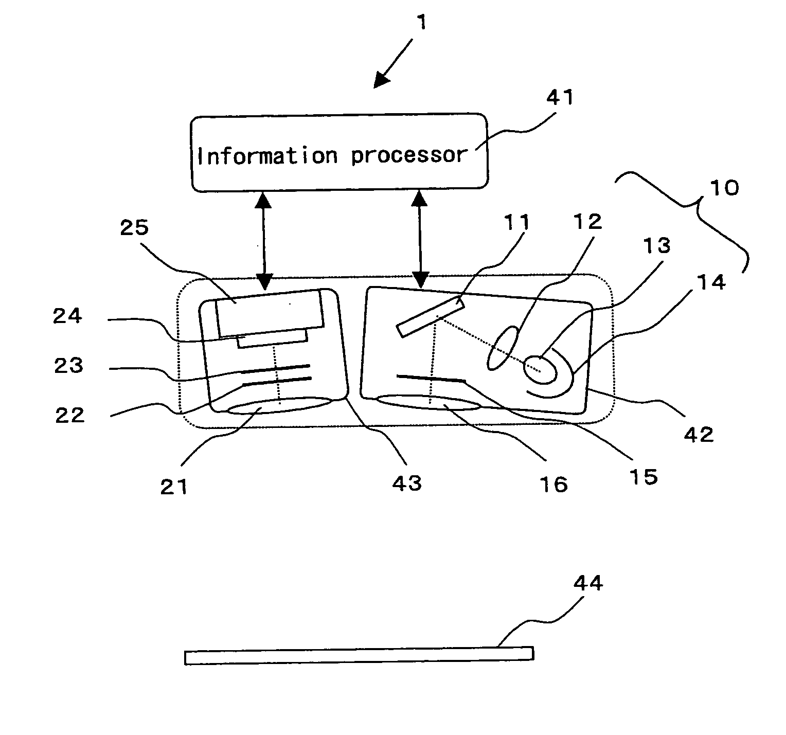
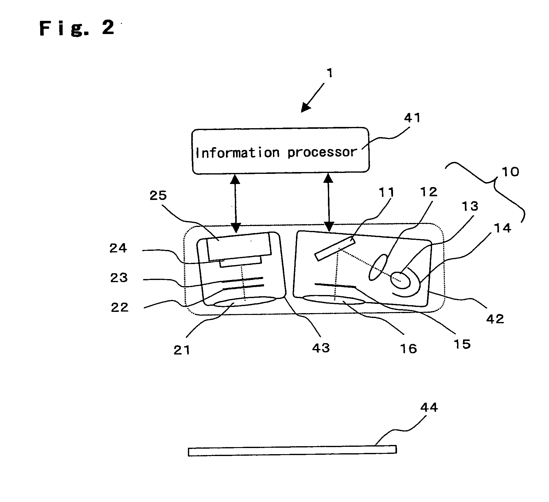
[0038]FIG. 2 is a schematic configurational view showing the first embodiment of a fluorescence detecting apparatus according to the present invention.
[0039] In this drawing, a fluorescence detecting apparatus 1 is comprised of an excitation light pattern generating illuminator 42, a fluorescence image detector 43 and an information processor 41.
[0040] In excitation light pattern generating illuminator 42, light from a light source 10 is irradiated on a micromirror array device 11, the light reflected off micromirror array device 11 passing through a projection lens 16 to be projected on a surface of detection 44 of a sample. Micromirror array device 11 is composed of a plurality of angle-variable micro mirrors as many number as the pixels of the projection image pattern, and the angle switching actions of individual micromirrors can be controlled by PWM (pulse width modulation) control to determine grayscales.
[0084]FIG. 5 is a schematic configurational view showing a fluorescence detecting apparatus according to the second embodiment of the present invention.
[0085] The fluorescence detecting apparatus of the second embodiment is comprised of an excitation light pattern generating illuminator 42a and a fluorescence image detector 43a, which are arranged so as to partly share a coaxial optical system, and an information processor 41.
[0086] In excitation light pattern generating illuminator 42a, light from a light source 10 is irradiated on a micromirror array device 11, the light is further reflected off micromirrors is reflected on a dichroic mirror 32, then passes through a main lens 31 to be projected on the surface of detection 44 of a sample. Micromirror array device 11 is composed of a plurality of angle-variable micro mirrors as many number as the pixels of the projection image pattern, and the angle switching actions of individual micromirrors ...
third embodiment
Description of the Third Embodiment
[0120]FIG. 6 is a schematic configurational view showing a fluorescence detecting apparatus according to the third embodiment of the present invention.
[0121] The fluorescence detecting apparatus of the third embodiment is comprised of an excitation light pattern generating illuminator 42b, a fluorescence image detector 43 and an information processor 41.
[0122] In excitation light pattern generating illuminator 42b, light emitted from a light source 10 passes through a transmission-type liquid crystal device 17 and to be projected to the surface of detection 44 of a sample via a projection lens 16.
[0123] Light source 10 is composed of a lamp 13, a light source mirror 14 arranged at the rear of the lamp and a light source lens 12 for irradiating light onto transmission-type liquid crystal device 17. Transmission-type liquid crystal device 17 is controlled by a control circuit in accordance with the excitation light pattern generating information s...
PUM
Abstract
A fluorescence detecting apparatus includes: a light source for illuminating the surface of detection of a sample with excitation light; a CCD area image sensor for detecting fluorescence emitted from the sample; and a micromirror array device for irradiating excitation light in a 2-dimensional illumination pattern generated by an information processor based on the detected result from the CCD area image sensor. In this configuration, irradiation of weak excitation light on areas that contain large amounts of fluorescent dyes hence would emit strong fluorescence makes it possible to excite reduced amounts of fluorescence and thereby inhibit adverse effects such as blurring or spreading of light of fluorescent wavelengths around the areas as well as to prevent the high-sensitivity fluorescence detecting device from being saturated by excessive amounts of light. On the other hand, irradiation of strong excitation light on areas that contain lower amounts of fluorescent dyes hence would emit weak fluorescence makes it possible to obtain high enough amounts of fluorescence that can be detected by the fluorescence detecting device.
Description
[0001] This Nonprovisional application claims priority under 35 U.S.C. §119(a) on Patent Application No. 2005-109906 filed in Japan on 6 Apr. 2005, the entire contents of which are hereby incorporated by reference. BACKGROUND OF THE INVENTION [0002] (1) Field of the Invention [0003] The present invention relates to a light detecting apparatus for detecting light intensity of fluorescence, reflected light, transmitted light, etc., obtained by illuminating an object under observation with light, and mainly relates to an apparatus which detects fluorescence distribution when excitation light is irradiated, in particular, relating to a fluorescence detecting apparatus for detecting 2-dimensional separation and development of a fluorescence-labeled sample by electrophoresis etc. [0004] (2) Description of the Prior Art [0005] Generally, methods for obtaining information of an object to be observed by an optical detecting means that illuminates an object under observation with light have b...
Claims
Application Information
Patent Timeline
Application Date:The date an application was filed.
Publication Date:The date a patent or application was officially published.
First Publication Date:The earliest publication date of a patent with the same application number.
Issue Date:Publication date of the patent grant document.
PCT Entry Date:The Entry date of PCT National Phase.
Estimated Expiry Date:The statutory expiry date of a patent right according to the Patent Law, and it is the longest term of protection that the patent right can achieve without the termination of the patent right due to other reasons(Term extension factor has been taken into account ).
Invalid Date:Actual expiry date is based on effective date or publication date of legal transaction data of invalid patent.

