Inductively-coupled plasma etch apparatus and feedback control method thereof

a plasma etching and feedback control technology, applied in electrical devices, light sources, electric discharge tubes, etc., can solve the problems of plasma apparatus without the function of plasma parameters feedback control, affecting the operation cost and product delivery, and unable to provide warning functions for manufacturing yield damage, etc., to improve the stability of the etching process, the effect of long and laborious r&d

Inactive Publication Date: 2006-10-12
NATIONAL TSING HUA UNIVERSITY
View PDF6 Cites 60 Cited by
  • Summary
  • Abstract
  • Description
  • Claims
  • Application Information

AI Technical Summary

Benefits of technology

[0032] As voltage / current measuring device of the inductively-coupled plasma etch apparatus of the present invention can apply to a commercial RF ohmmeter to directly measure the ion current and RF voltage, no lengthy and laborious R&D is required. Therefore, the current problem that can not be immediately feedback controlled can be improved. The interference due to differences of device configurations and changes of the outside environment can be removed so as to improve the stability of the quality of the etching process.

Problems solved by technology

However, the current monitor system does not provide a warning function to prevent the manufacturing yield from damages until during the steps of device testing or subsequent wafer checking and measuring.
Thus, when the problem occurs, thousands of wasted wafers need to be thrown away that will severely impact the operational cost and product delivery.
However, all the current plasma apparatus has no such function of plasma parameters feedback controls.
Therefore, when the reaction chamber in the plasma apparatus is interfered by the outside environment or the internal walls of the cavity have changed, there is no way to real-time adjust the output of the RF power generators to meet the predefined plasma status according to the actual plasma status in reaction chamber.
However, since there is only one RF power generator, the two plasma parameters of ion current and RF bias voltage in the reaction chamber can not be controlled simultaneously.

Method used


Image

  • Inductively-coupled plasma etch apparatus and feedback control method thereof
  • Inductively-coupled plasma etch apparatus and feedback control method thereof
  • Inductively-coupled plasma etch apparatus and feedback control method thereof

Examples


Embodiment Construction

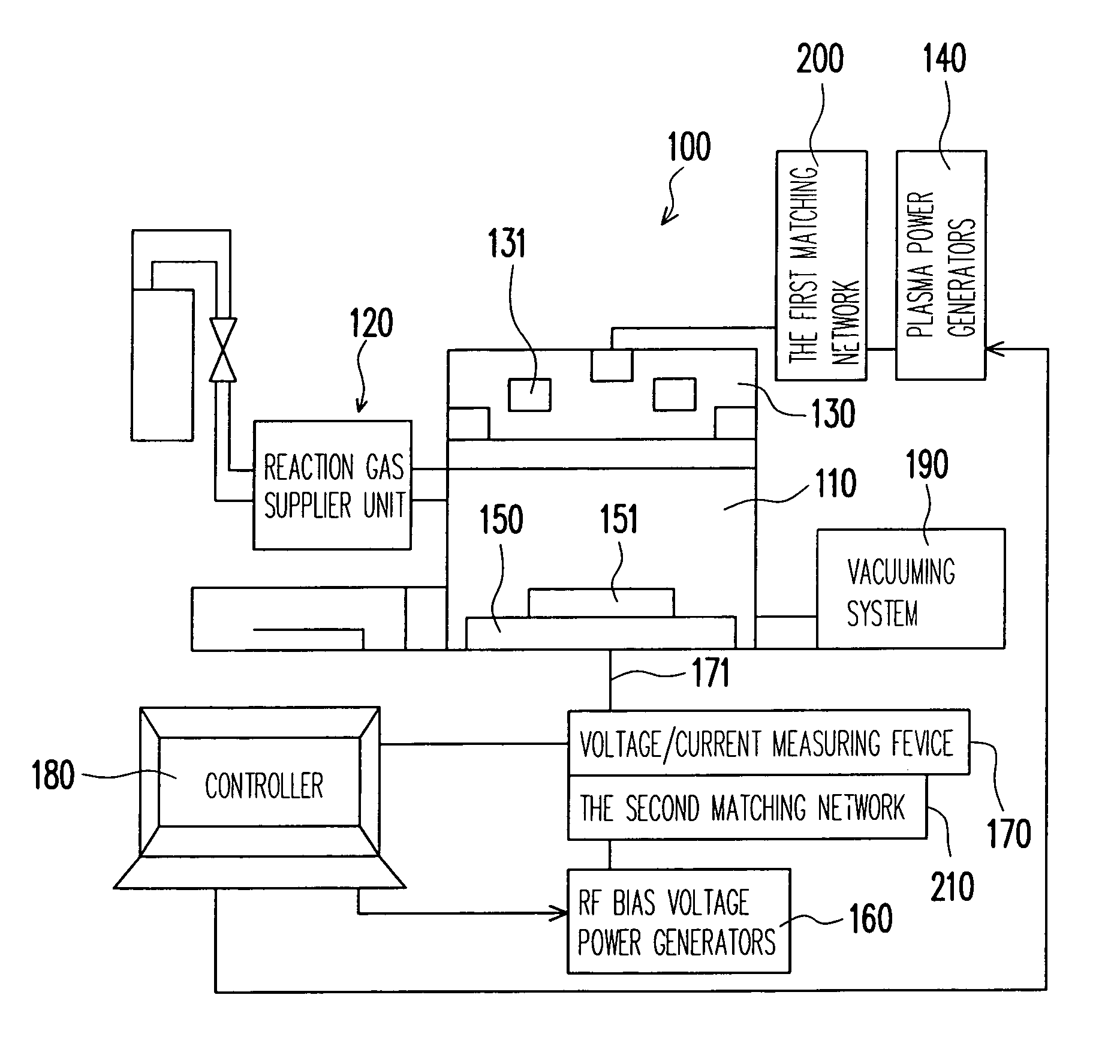
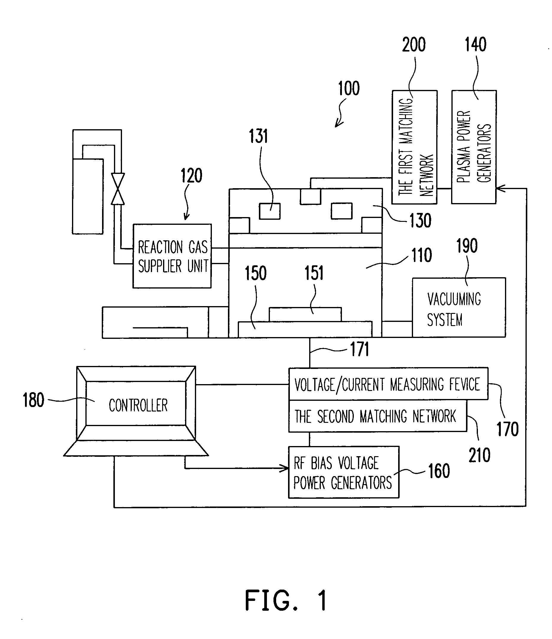
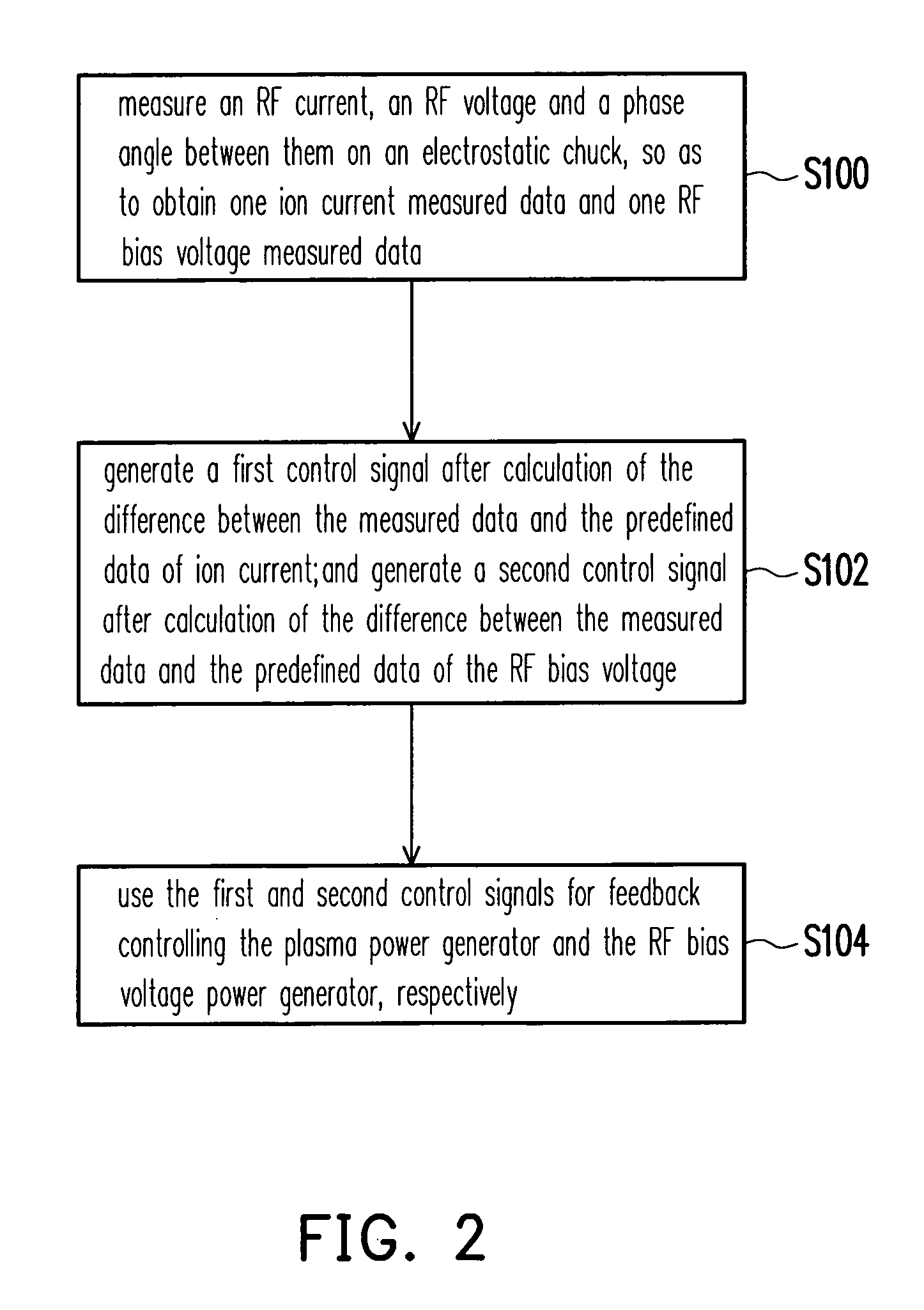
[0043] Please refer to FIG. 1 which is a system schematic block diagram of an inductively-coupled plasma etch apparatus of the present invention. The present invention measures the RF current, the RF voltage and the phase angle between them of the electrostatic chuck 150 in real operation within a reaction chamber 110 of etching device by a voltage / current measuring device 170, so as to obtain an ion current measured data and an RF voltage measured data. And the controller 180 generates a first control signal by calculation of the difference between the measured ion current and the preferred ion current; and generates a second control signal by calculation of the difference between the measured RF voltage and the preferred RF voltage. Then, the first control signal and the second control signal feedback control the plasma power generator 140 and RF bias voltage power generator 160, so to achieve desired plasma in the reaction chamber 110.

[0044] The inductively-coupled plasma etch a...


PUM


Abstract

An inductively-coupled plasma etch apparatus and a feedback control method thereof are provided. A voltage/current measuring device is connected to an electrostatic chuck of the plasma etching apparatus, so as to measure the RF current, voltage and the phase angle between them on the electrostatic chuck. The ion current and the RF bias voltage are obtained by calculation of the RF current, voltage and the phase angle. Finally, using the obtained ion current and the RF bias voltage to feedback control the RF power generator in order to achieve the desired plasma status.

Description

CROSS-REFERENCE TO RELATED APPLICATION [0001] This application claims the priority benefit of Taiwan application serial no. 94111444, filed on Apr. 12, 2005. All disclosure of the Taiwan application is incorporated herein by reference. BACKGROUND OF THE INVENTION [0002] 1. Field of Invention [0003] The present invention relates to a plasma etch apparatus and a feedback control method thereof. More particularly, the present invention relates to a plasma etch apparatus and a feedback control method thereof with feedback controlled ion current and RF bias voltage. [0004] 2. Description of Related Art [0005] Among the integrated circuit manufacturing apparatuses, the cost of plasma manufacturing apparatus is about 30%-40% of the overall cost; and most of them are apparatuses with high unit price (the unit price may be over NTD 100,000,000). The apparatuses include plasma etching apparatus, plasma chemical gas depositing apparatus, plasma physical gas depositing apparatus, light resistan...

Claims


Application Information

Patent Timeline
Patent Type & Authority Applications(United States)
IPC IPC(8): H01J7/24
CPCH01J37/3299H01J37/321
Inventor LIN, CHAUNGLEOU, KEN-CHYANGCHANG, CHENG-HUNGHSIAO, KAI-MU
Owner NATIONAL TSING HUA UNIVERSITY
Why Eureka
Try Eureka