

Time-of-flight measurement using pulse sequences
- Summary
- Abstract
- Description
- Claims
- Application Information
AI Technical Summary
Benefits of technology
Problems solved by technology
Method used
Image

Examples
Embodiment Construction
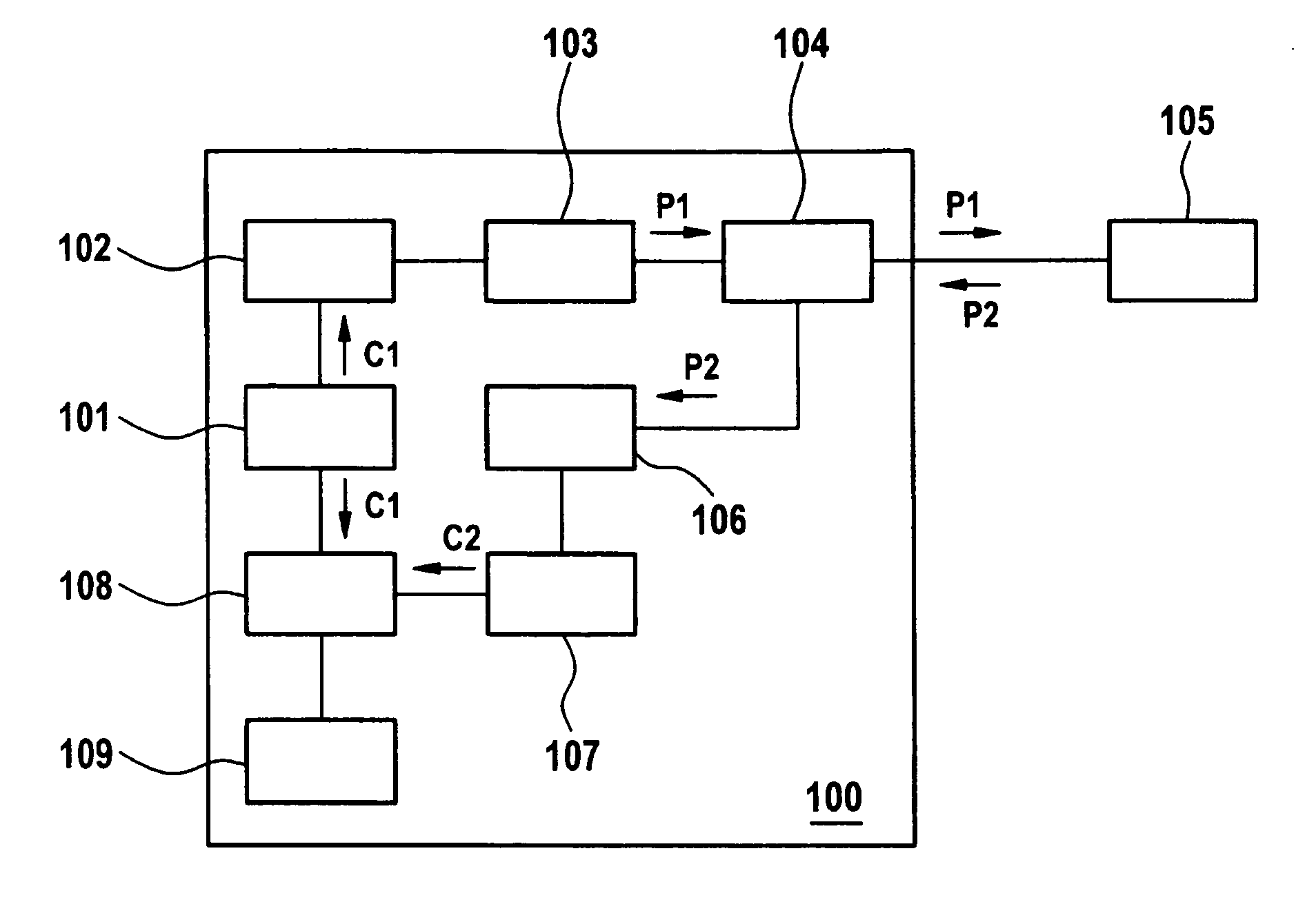
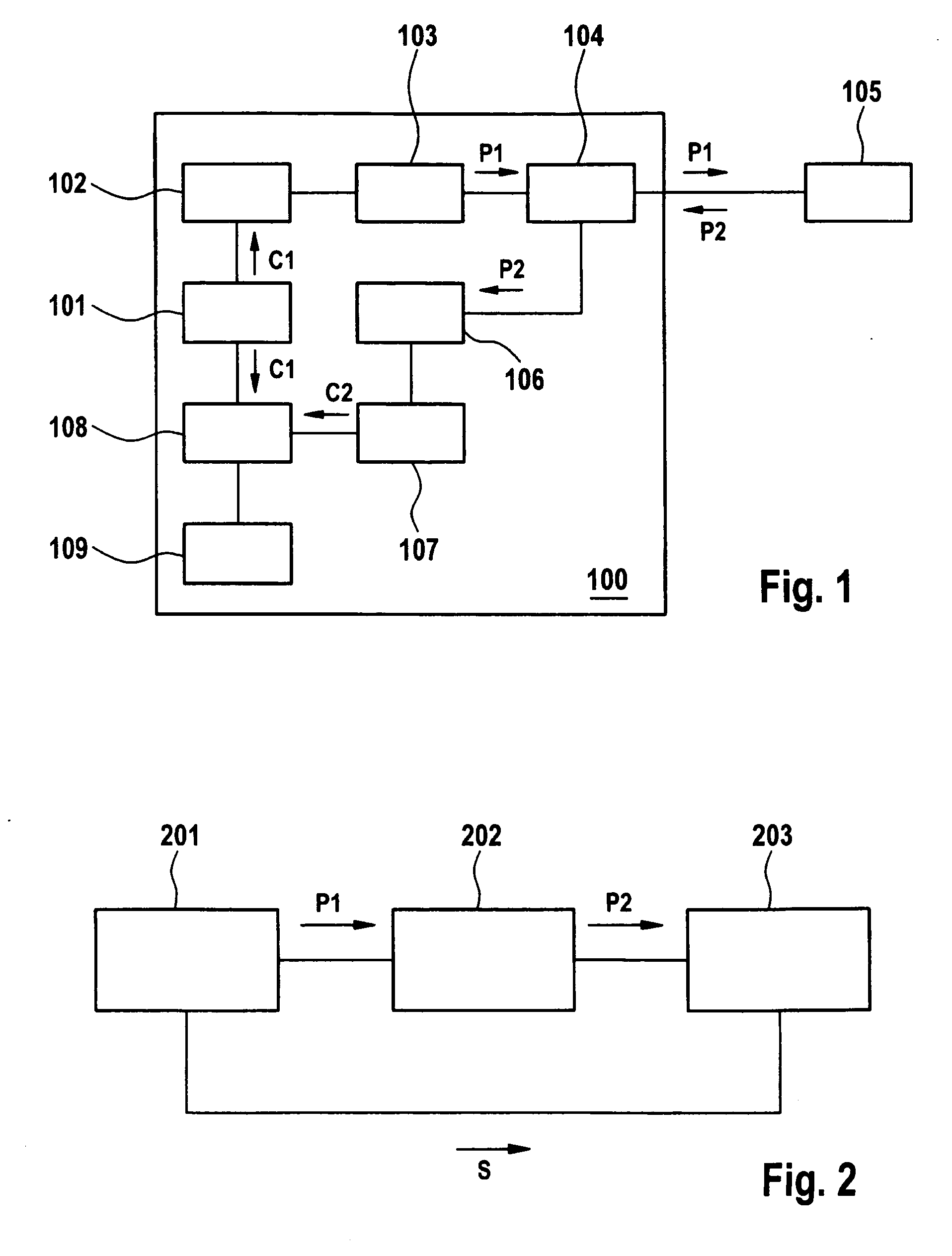
[0022]FIG. 1 shows an exemplary block diagram of an optical measurement setup with an optical time domain reflectometer (OTDR) 100 and a device under test (DUT) 105. The OTDR 100 comprises a code generator 101, a laser driver 102, a light source 103 preferably realized as a laser transmitter, a bidirectional optical coupler 104, an optical detector 106, an Analog-to-Digital converter (ADC) 107, a digital signal processor (DSP) 108, and a main processor 109. The optical coupler connects the laser transmitter 103, the DUT 105, and the detector 106.
[0023] A first code or digital sequence C1 is stored in a memory (ROM) and fetched by the code generator 101. The code generator 101 provides a control signal to light source driver 102 so that light source driver 102 provides electrical pulses to light source 103 according to the first code C1. The electrical pulses form a determined digital sequence, causing light source 103 to generate a sequence of light pulses in accordance with the se...
PUM
 Abstract
Description
Claims
Application Information