Thermal deposition coating method

a coating method and thermal deposition technology, applied in heat treatment equipment, process and machine control, instruments, etc., can solve the problems of overheating of coating and workpieces, thermal degradation, damage to thermal stresses, etc., to achieve excellent coating production rates, reliable thermal measurement, and minimize damage to internal stresses

Active Publication Date: 2006-10-12
AIR PROD & CHEM INC
View PDF9 Cites 111 Cited by
  • Summary
  • Abstract
  • Description
  • Claims
  • Application Information

AI Technical Summary

Benefits of technology

[0025] Advantages can be achieved based upon the control process for forming coatings on thermally conductive substrates by thermal deposition coating methods employing cryogenic coolants and they may include one or more of the following: an ability to achieve excellent coating production rates without the risk of overheating and thermally damaging the substrate material; an ability to produce well adhering, uniform coatings on workpieces while minimizing damaging internal stress...

Problems solved by technology

Improper temperature control during thermal deposition frequently, leads to coating and workpiece overheating, thermal degradation, and damaging thermal stresses due to a mismatch of thermal contraction coefficients between the coating and substrate surface.
When damage occurs through overheating, thermal stress and the like, the resulting coatings may be poorly adhering, or even fractured.
Cooling air jets are often used to offset the loss of process productivity due to such a practice but (a) air cooling ...

Method used


Image

  • Thermal deposition coating method
  • Thermal deposition coating method
  • Thermal deposition coating method

Examples


example 1

Cylindrical Workpiece

[0078] The purpose of this example is to more fully explain the control parameters enumerated in the description of the process steps shown in FIG. 6. FIGS. 4, 5 and 6 are used to facilitate the description.

[0079]FIG. 4 illustrates a thermal deposition process employing a workpiece 40 comprised of a workpiece substrate surface 41 which has cylindrical shape and which is rotated during the thermal deposition coating process. The workpiece (RW) comprised of workpiece substrate surface 41 is mounted in a remotely actuated, rotating holder (RWA) 42, and exposed to hot coating deposition material 46 from the thermal deposition head (TCD) 44 which, in turn, traverses over the workpiece surface by the means of a separate actuated holder (TCDA). Traversing in sync with thermal deposition head 44 is an elongated, cryogenic coolant distributor (SCMD) 48 which provides the cooling effect either to the coated only portion of the substrate 41 or to the uncoated and coated ...

example 2

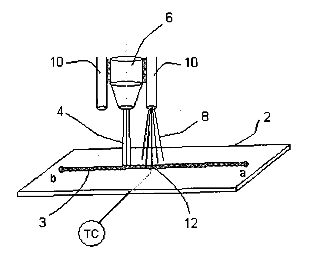
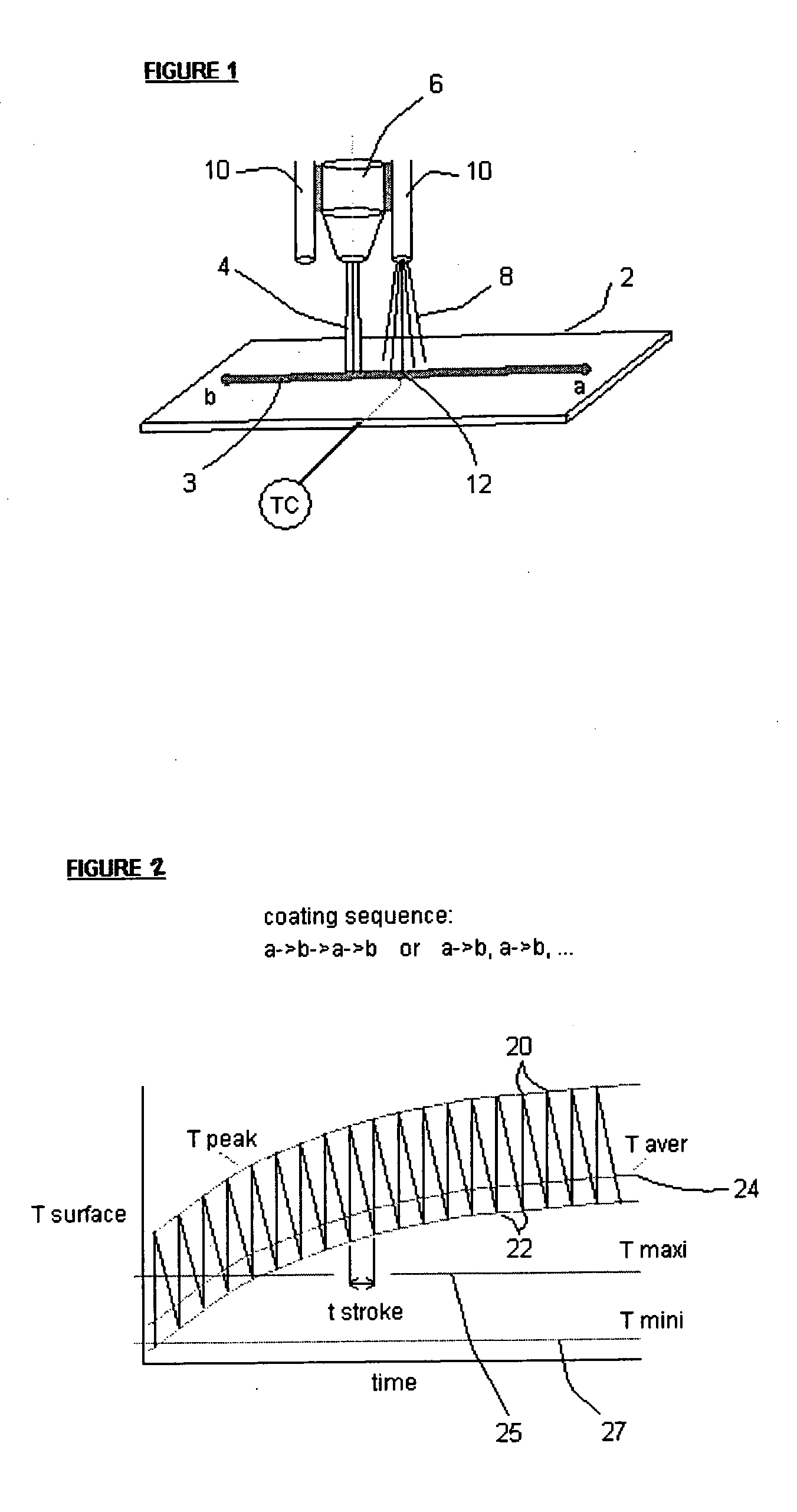
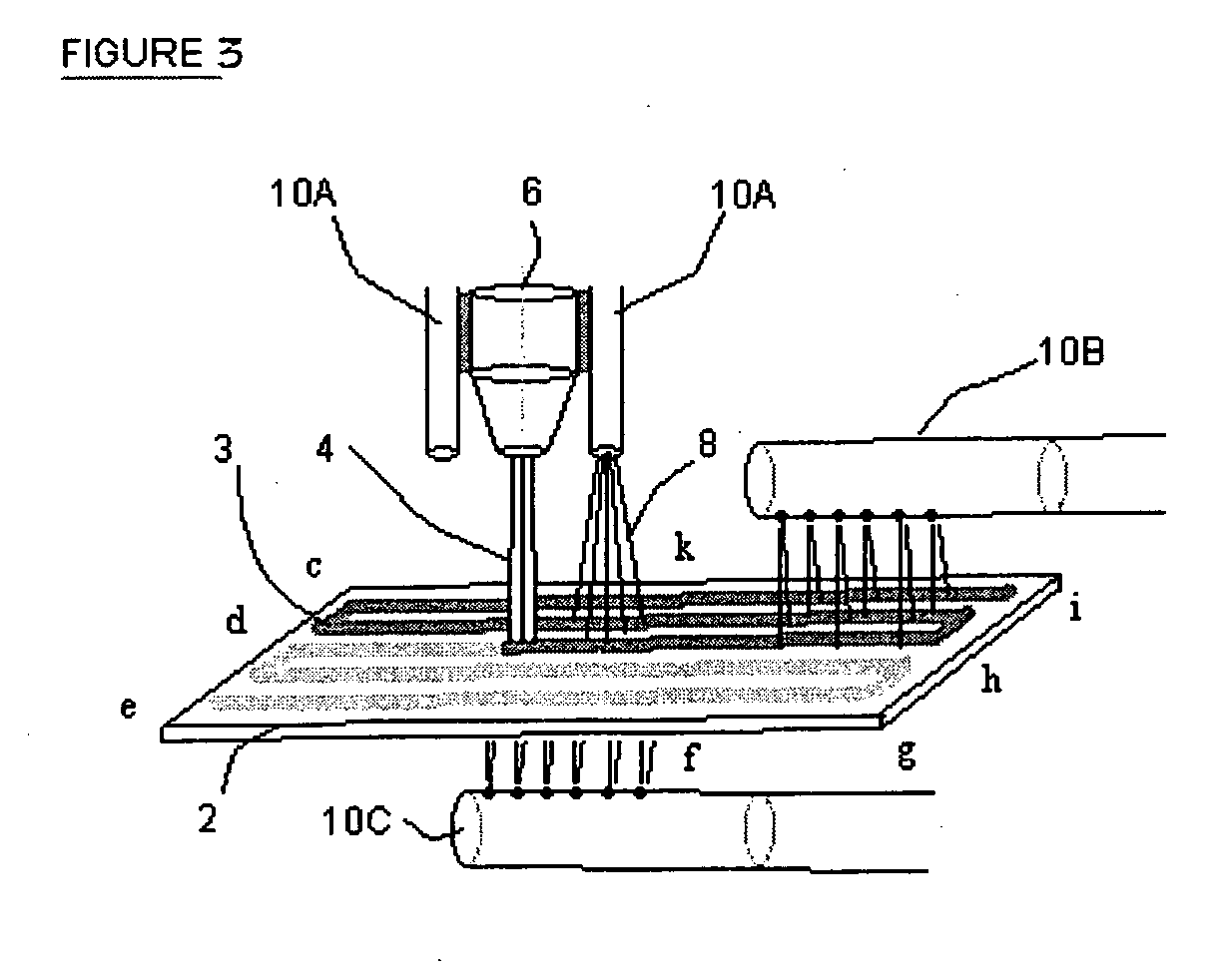
[0088]FIG. 3 is a view of a thermal deposition process employing, optionally, both traversing and stationary cryogenic coolant delivery systems for the workpiece. Common pieces of equipment to those shown in FIG. 1 are similarly numbered. In showing a method for establishing cooling in the thermal deposition coating operations using a cryogenic gas coolant media, one or more coolant means 10A, 10A′, 10B and 10C provide a coolant 8. These coolant means, such as 10A, 10A′ may move with thermal deposition head 4, move as the distributor 48 shown in FIG. 4 moves, or remain stationary. Cooling the top side of the workpiece, that is the surface of the workpiece to be coated, where the heat is deposited with coating material is more desired than cooling the back side of the workpiece because of the resultant stress distribution. Of course, cooling the top side of the workpiece surface, whether the cooled portion of the surface was already coated or not, is more difficult. In one embodiment...


PUM

PropertyMeasurementUnit
Temperatureaaaaaaaaaa
Flow rateaaaaaaaaaa
Deposition rateaaaaaaaaaa

Abstract

A process for the thermal deposition coating of a workpiece, said process comprising the steps of: (c) thermally depositing a coating on a metallic surface of a workpiece from a deposition head wherein at least one condition selected from the group of: coating deposition rate onto said surface, relative motion between the surface and said deposition head, and cryogenic coolant application rate onto said workpiece is controllable; (d) substantially simultaneously measuring temperatures at a plurality of locations over the metallic surface of the workpiece; (c) determining an average temperature of the temperatures measured in step (b); (d) comparing the average temperature to a preselected minimum temperature and a preselected maximum temperature for the workpiece; and (e) adjusting at least one of the controllable conditions if said average temperature is not between the preselected minimum temperature and the preselected maximum temperature for the workpiece. Standard deviations of all temperature readings and controlling the relative motion speed between the thermal coating deposition head and the workpiece provide another improvement for obtaining temperature uniformity over the workpiece surface.

Description

[0001] This application claims priority to a provision application 60 / 670,497, filed Apr. 12, 2005, entitled “Control Method for Thermal Deposition Coating Operations, which is incorporated in its entirety herein by reference.BACKGROUND OF THE INVENTION [0002] Processes for applying various coatings such as metallic, alloy, ceramic and composite to a variety of substrates to form component products using thermal deposition coating methods are known. Such processes are employed to improve properties of the substrate such as hardness, corrosion resistance, heat resistance surface porosity and the like. Exemplary thermal deposition coating operations include: high-velocity oxy-fuel spraying (HVOF) and high-velocity air-fuel spraying (HVAF), DC and RF plasma spray in air atmosphere, vacuum chamber and / or inert gas chamber, electric arc (twin and single wire) spraying, laser powder coating or cladding, transferred arc coating operations such as plasma transferred-arc powder coating and w...

Claims


Application Information

Patent Timeline
IPC IPC(8): C23C16/52
CPCC21D1/613C21D1/667B05B13/0468G05D23/2723Y02T50/67C23C4/12G05D23/1928G05D23/27C23C4/00Y02T50/60
Inventor ZURECKI, ZBIGNIEW
Owner AIR PROD & CHEM INC
Why Eureka
Try Eureka