Temperature swing adsorption system

a technology of adsorption system and temperature swing, which is applied in the field of adsorption system, can solve the problems of acid rain and global warming, no economical means to collect cosub>2 /sub>emissions from power plants or other point sources, and energy production from combustion of fossil fuels. , to achieve the effect of high shear stress

Active Publication Date: 2006-10-19
ADSORPTION RES
View PDF13 Cites 37 Cited by
  • Summary
  • Abstract
  • Description
  • Claims
  • Application Information

AI Technical Summary

Benefits of technology

[0047] The effect of shear stress is severe for particles that are spherical beads, since those tend to contact neighboring particles and adjacent solid surfaces nearly at a single point (or very small fraction of the total surface area); hence, the normal force exerted at that point results in a very high pressure (normal force / contact area), which produces a correspondingly high shear stress. Since it is the nature of moving bed adsorbent systems for all of the adsorbent to pass through the region where shear forces are highest while completing each pass through the system, it is critical to ensure that the highest shear force is appropriately low, to keep the cumulative effects of shear (and attrition) to an acceptable level.

Problems solved by technology

One problem of our modern society is energy production from combustion of fossil fuels, and the associated emissions.
Though there remains some controversy, the two key problems associated with such emissions are acid rain and global warming.
At present, there is no economical means to collect CO2 emissions from power plants or other point sources.
Coupled with the perceived problem of climate change is the gradual depletion of fossil energy sources, such as, for example, crude oil.
As reported by Treybal “Several adsorbers on a very large scale were built, but the very brittle carbon was subject to serious attrition losses, and no new continuous-flow, countercurrent device for plug flow of solids and gas is believed to be in operation.” (Treybal, R. E., “Mass-Transfer Operations,” 3rd Ed., McGraw-Hill, New York, 1980).
The trays are perforated, but the holes are too small for the adsorbent to penetrate.
At present, however, state-of-the-art technologies for existing power plants are essentially limited to ‘amine absorbents’.” (http: / / www.netl.doe.gov / coal / Carbon%20Sequestration / Resources / faqs.html, Jan. 5, 2005).
Any of these other technologies that rely on compression or evacuation (e.g., pressure swing adsorption, membrane processes, and some versions of absorption), are hindered by the inherent cost of that operation.
If the flue gas must be compressed in order to treat it (e.g., via a membrane unit), the power cost will depend on the required pressure.
Likewise, if vacuum must be used to collect the concentrated CO2, the cost will depend on the extent of evacuation.

Method used


Image

  • Temperature swing adsorption system
  • Temperature swing adsorption system
  • Temperature swing adsorption system

Examples


examples

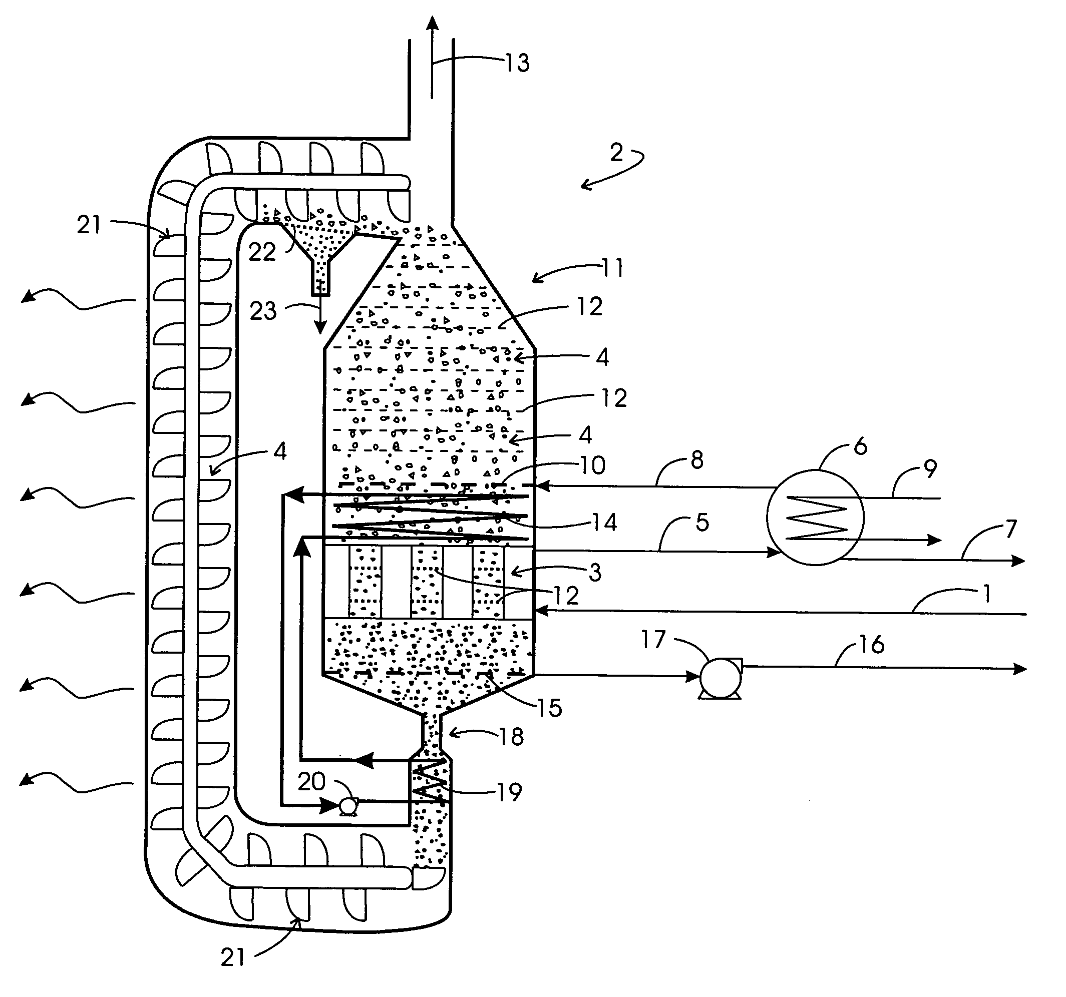
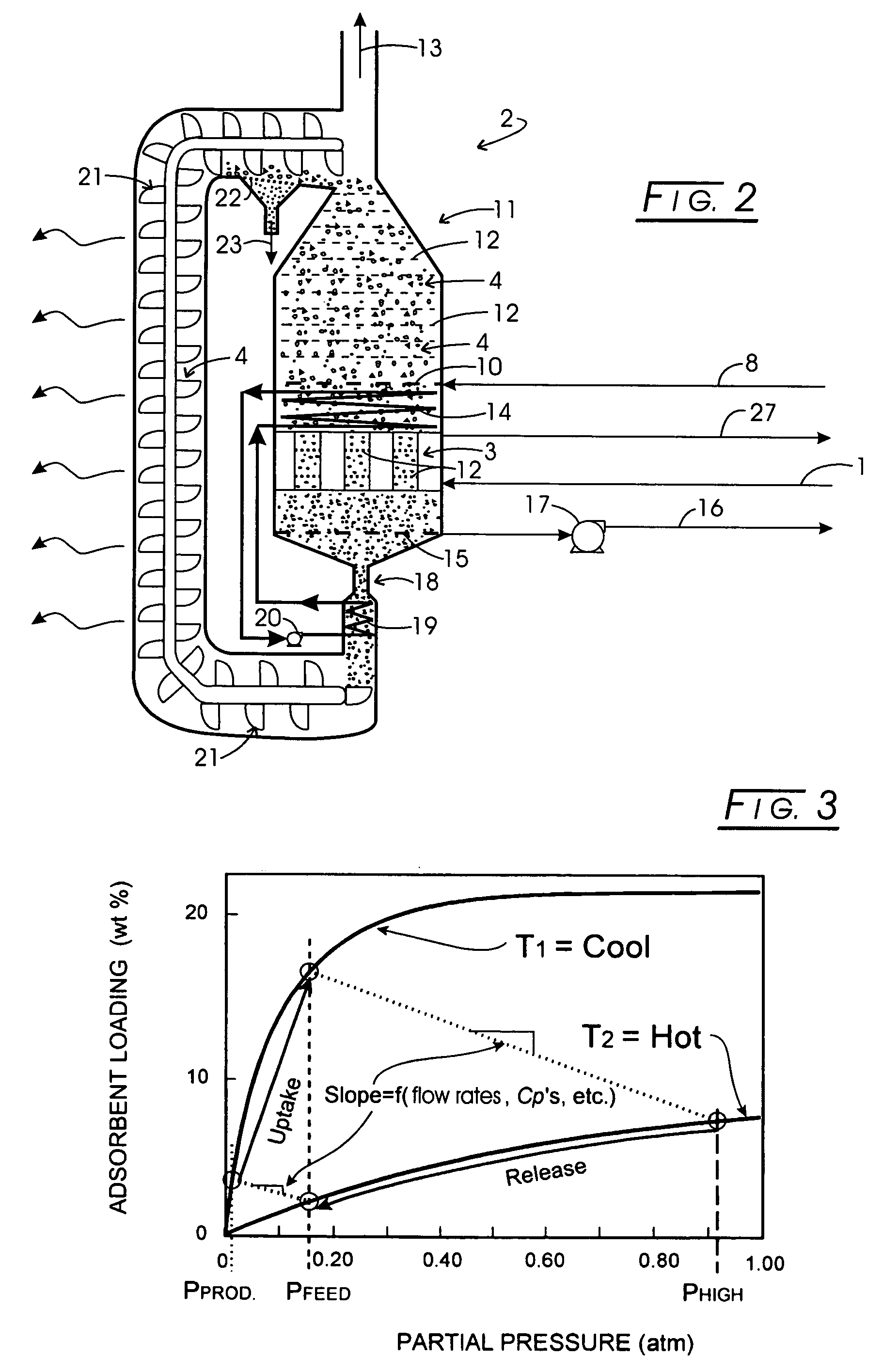
[0069] An experimental apparatus was assembled to test the basic concepts of this invention, and is shown in FIG. 6 with the reference numerals corresponding to those in FIGS. 1 and 2. The purpose of the example is to remove CO2 from simulated flue gas. In this case, CO2 is the SAC. The example, and in particular, the apparatus does not does not fully embody some of the mechanical features of the invention, which are impractical to employ on a laboratory scale. For example, it does not employ a conveyor (21 in FIG. 1) in the ordinary sense of the word. Rather reservoirs were constructed that could be interchanged, so as the adsorbent supply reservoir, 24, a collection reservoir filled, 25, and by employing a spare, it was possible to operate virtually without interruption. In addition, it was not practical to employ a combustion source for heat, but rather a hot oil heat source, 26, was circulated through the heat exchanger, as described under “Option 2: Ancillary hot media is heat ...


PUM

PropertyMeasurementUnit
temperatureaaaaaaaaaa

Abstract

A method for removing one or more strongly adsorbed components (SAC) from a process gas stream having SAC and other gaseous components adjusts the temperature of the SAC-laden process gas stream to be between about 80° and about 500° C. The temperature-adjusted process gas stream is contacted with a heat-exchange surface to transfer heat to an adsorbent, thus causing adsorbed SAC to be desorbed for collection, and to cool the process gas stream and remove any condensate from the cooled process gas stream. The cooled process gas stream is contacted with a cooled section of the adsorbent to adsorb SAC therefrom, producing a SAC-depleted process gas stream and a SAC-laden adsorbent. Desorbed SAC is withdrawn for collection and any adsorbent fines are withdrawing for collection.

Description

CROSS-REFERENCE TO RELATED APPLICATIONS [0001] None STATEMENT REGARDING FEDERALLY SPONSORED RESEARCH [0002] Not applicable. BACKGROUND OF THE INVENTION [0003] 1. Field of the Invention [0004] The present invention relates to an adsorber to capture and enrich carbon dioxide (CO2) from flue gas and having a unique moving bed structure in which regeneration occurs by heating the adsorbent. This type of system is commonly referred to as temperature swing adsorption (TSA), since the adsorbent temperature is cycled synchronously during uptake and release. This particular type of TSA concept involves a moving bed of adsorbent. It offers significant advantages such as, for example, higher efficiency, lower thermal mass, lower heat loss, and lower cost than fixed bed (stationary adsorbent) systems employed to achieve the same end. This type of adsorber is especially well suited to applications where flue gas contains at least 3% carbon dioxide, and at least 1,000 standard cubic feet per hour...

Claims


Application Information

Patent Timeline
Patent Type & Authority Applications(United States)
IPC IPC(8): B01D53/02
CPCB01D53/0462Y02E50/346B01D53/261B01D2253/102B01D2253/104B01D2253/106B01D2253/108B01D2253/116B01D2253/304B01D2256/10B01D2256/24B01D2256/245B01D2257/302B01D2257/404B01D2257/504B01D2257/602B01D2257/702B01D2257/80B01D2259/40007B01D2259/40098Y02C10/08B01D53/08Y02C20/40Y02E50/30
Inventor KNAEBEL, KENT S.
Owner ADSORPTION RES
Why Eureka
Try Eureka