Microfluidic method and device for transferring mass between two immiscible phases

a microfluidic and immiscible technology, applied in the direction of semi-permeable membranes, material analysis by electric/magnetic means, electrolysis components, etc., can solve the problems of unstable plane interface between the two fluids and complex implementation

Inactive Publication Date: 2006-10-19
COMMISSARIAT A LENERGIE ATOMIQUE ET AUX ENERGIES ALTERNATIVES
View PDF6 Cites 131 Cited by
  • Summary
  • Abstract
  • Description
  • Claims
  • Application Information

AI Technical Summary

Benefits of technology

[0006] The idea on which the present invention is based is to cause a droplet (having a volume of microliter order, or of the order of hundreds or even tens of nanoliters) of a liquid first phase to travel inside a larger volume (e.g. lying in the range about ten microliters to a few milliliters) of a fluid (liquid or gaseous) second phase by using a microfluidic device of the “fluidic chip” type. The term “microfluidic device” is used therein to mean a device enabling liquid to be manipulated in volumes of less than one milliliter, typically lying in the range a few hundreds of nanoliters to a few hundreds of microliters. Such devices can be mass produced at very low cost by using fabrication techniques that are derived from microelectronics, such as photolithography and thin layer deposition. Another advantage of this technique lies in the fact that a chip type device can include analysis devices integrated therein.

Problems solved by technology

The transfer of solute from one phase to the other takes place through the pores in the membrane, without which the plane interface between the two fluids would be unstable.
However it is complex to implement since it requires tricky assembly of discrete microfluidic elements.

Method used


Image

  • Microfluidic method and device for transferring mass between two immiscible phases
  • Microfluidic method and device for transferring mass between two immiscible phases
  • Microfluidic method and device for transferring mass between two immiscible phases

Examples


Embodiment Construction

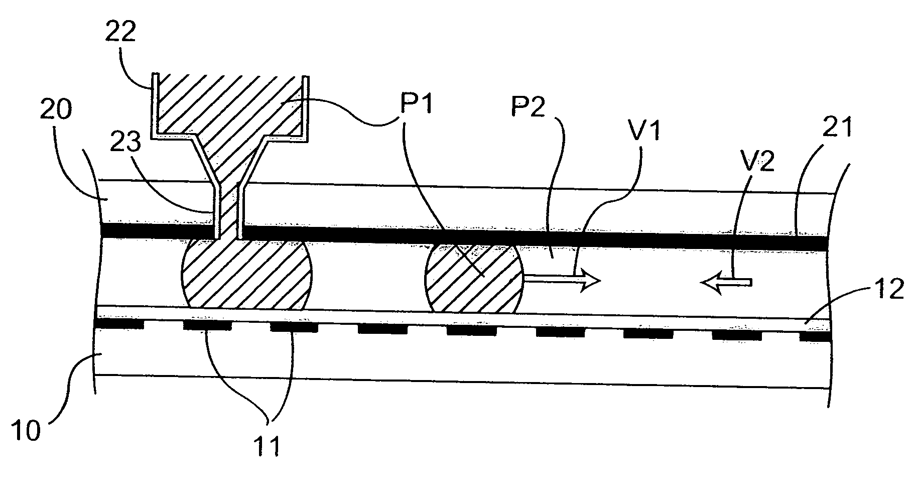
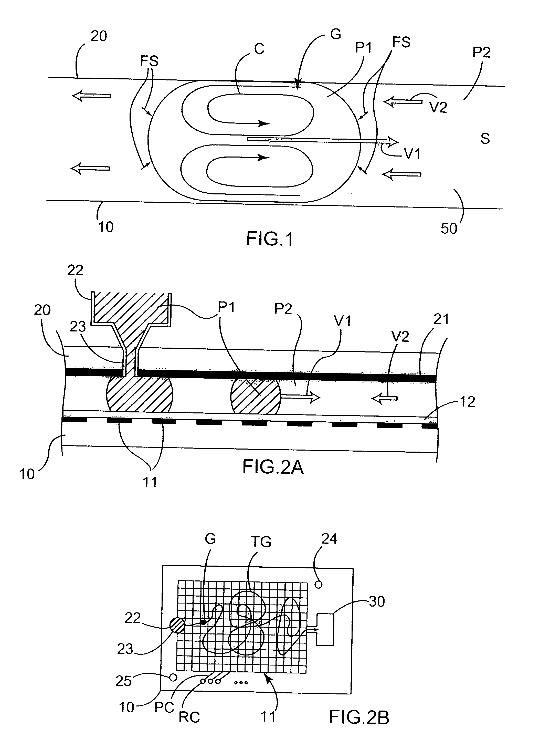
[0038] The principle on which the invention is based can be understood with the help of FIG. 1. A droplet G of a liquid first phase P1 having a volume lying in the range 10 nl to 10 μl, for example, and preferably in the range 100 nl to 1 μl, is placed in a space 50 extending between a bottom plate 10 and a top plate 20, and is immersed in a fluid second phase P2 that is immiscible with the first phase. For example, the first phase P1 may be constituted by an organic solvent such as chloroform or carbon tetrachloride, while the second phase P2 is an aqueous solution. The second phase P2 initially contains a solute S that presents high affinity for the first phase P1. The solute S may be constituted by atoms, ions, simple or complex molecules, cells, or biological entities such as viruses. The solute may also have an affinity for one of the ingredients of the phase P1. A chemical complex or a precipitate incorporating S then forms in the receiving phase P1. The solute S may be also b...


PUM

PropertyMeasurementUnit
volumeaaaaaaaaaa
volumeaaaaaaaaaa
volumeaaaaaaaaaa

Abstract

A method of transferring mass of at least one solute between a liquid first phase and a fluid second phase that is immiscible with the first phase, the method comprising moving at least one droplet of said liquid first phase in a microfluidic device by using electric-type forces (electrowetting or dielectrophoresis) within a space that is filled with said fluid second phase. Said droplet is preferably moved by said electric-type forces along a path between a point for injecting said droplet into said microfluidic device, and an extraction and / or analysis zone, said path being defined in such a manner that said droplet sweeps through a significant fraction of said space filled with said fluid second phase. The method may include a step of transferring said droplet using said electric-type forces to a chemical analysis device integrated in said microfluidic device, and a step of chemically analyzing said droplet. The invention also provides a device for implementing such a method.

Description

[0001] The invention relates to a method of transferring mass between two immiscible phases, in particular for liquid-fluid extraction, mainly in analytic applications. BACKGROUND OF THE INVENTION [0002] Liquid-fluid extraction is a unitary operation commonly used in industrial chemistry and in analytical chemistry, and it consists in causing mass of at least one solute to be transferred between a liquid first phase and a fluid (liquid or gaseous) second phase that is immiscible with the first. It is well known that in order to encourage such transfer, it is necessary to maximize the ratio of the contact area between the phases divided by the volume of the phases. Typically, that is achieved by dispersing one of the phases in the other, e.g. in a beaker and using a magnetic stirrer, followed by the phases separating out by settling. [0003] International patent document WO 96 / 12540 discloses a method of transferring solute between two non-miscible fluid phases through a plane porous ...

Claims


Application Information

Patent Timeline
Patent Type & Authority Applications(United States)
IPC IPC(8): C07K1/26G01N27/00
CPCB01D11/0496B01D11/04
Inventor SARRUT, NICOLASJEANSON, HUBERT
Owner COMMISSARIAT A LENERGIE ATOMIQUE ET AUX ENERGIES ALTERNATIVES
Why Eureka
Try Eureka