Apparatus and method for detecting and removing moisture and contaminants in a fuel storage tank

a technology for fuel storage tanks and apparatuses, which is applied in lighting and heating apparatus, multi-stage water/sewage treatment, separation processes, etc., can solve the problems of irate motorists, water has this nasty habit of getting into places where it does not belong, operation and maintenance problems reach critical mass, etc., and achieve accurate detection and measurement

Inactive Publication Date: 2006-10-19
ARILD & SHELLYS
View PDF6 Cites 13 Cited by
  • Summary
  • Abstract
  • Description
  • Claims
  • Application Information

AI Technical Summary

Benefits of technology

[0022] A principal object and advantage of the present invention is that moisture and contaminants in a fuel tank can be accurately detected at any location in the tank.
[0023] Another principal object and advantage of the present invention is that the amount of contaminated fuel removed can be accurately measured.
[0024] Another principal object and advantage of the present invention is that it is not necessary to remove all fuel from the tank in order to rid the fuel of moisture and contaminants.

Problems solved by technology

Water has this nasty habit of getting into places where it does not belong.
That water needs to be removed before it gets sucked into a motor vehicle's fuel tank, which can lead to irate motorists.
The operation and maintenance issues reach critical mass when ethanol combines with water and microscopic matter.
Tanks with poor housekeeping are likely to see a buildup of sludge in conjunction with the water.
Filters can be clogged frequently, product flow to the vehicle slows down, and the quality of fuel diminishes when such microbes begin to feed and grow in the water layer trapped at the tank bottom.
In the case of steel, the microbes, or bugs, can create a corrosive environment.
In plastic tanks where a high alcohol content has led to phase separation at the tank bottom, the plastic is subject to softening and can experience a reduction in its strength properties.

Method used


Image

  • Apparatus and method for detecting and removing moisture and contaminants in a fuel storage tank
  • Apparatus and method for detecting and removing moisture and contaminants in a fuel storage tank
  • Apparatus and method for detecting and removing moisture and contaminants in a fuel storage tank

Examples


Embodiment Construction

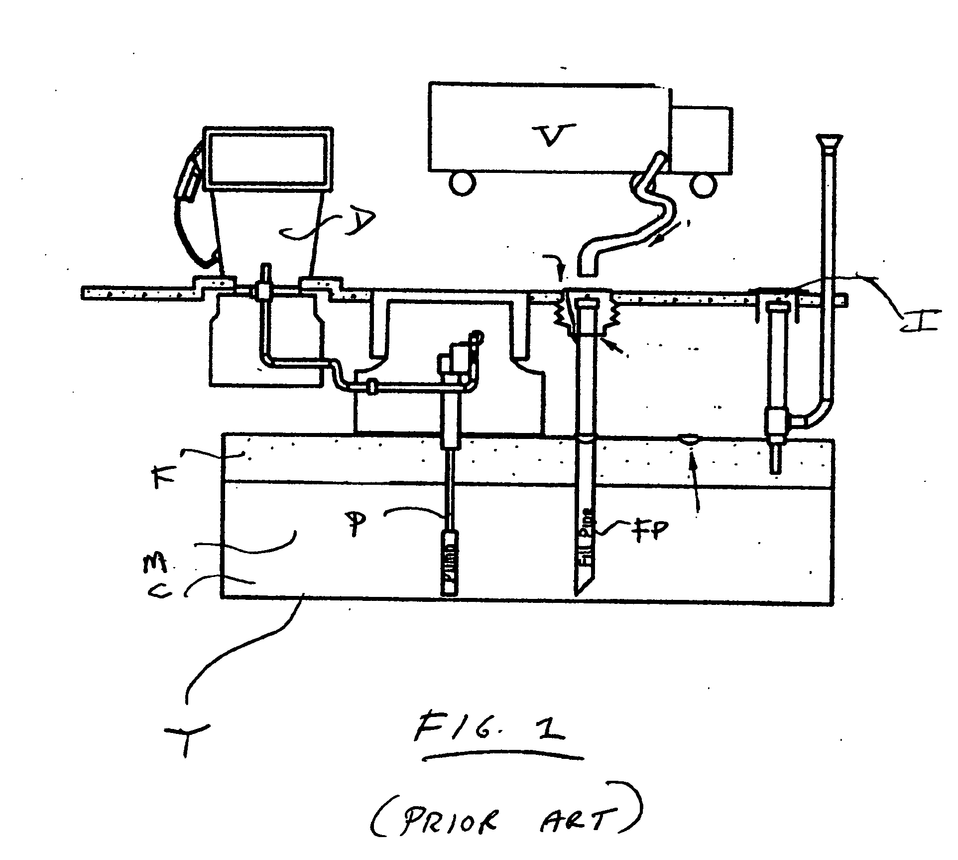
[0030] The environment in which the present invention operates and to which the objects and advantages of the present invention apply is shown in FIG. 1. A fuel storage tank T may be either above ground or underground (an underground tank is shown in the Figure). The tank T has a pump P for pumping fuel out of the tank to a fuel dispenser D. A fill pipe FP is used to add fuel to the tank T, for example but not exclusively, from a vehicle V. An inspection port I allows access to the tank for inspection of the tank and its contents. Fuel F is stored in the tank T. Moisture M, such as liquid water, and other contaminants C may also be present in the tank. Typically, the fuel F will be on top of the moisture M because of the relative specific gravities. Contaminants C may either be in the moisture M or suspended in the fuel F.

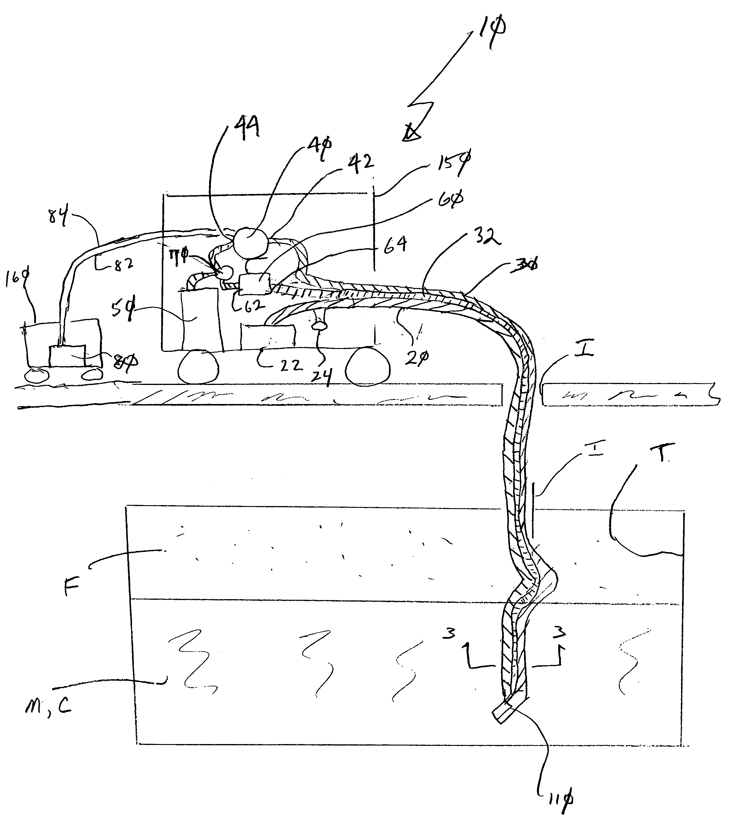
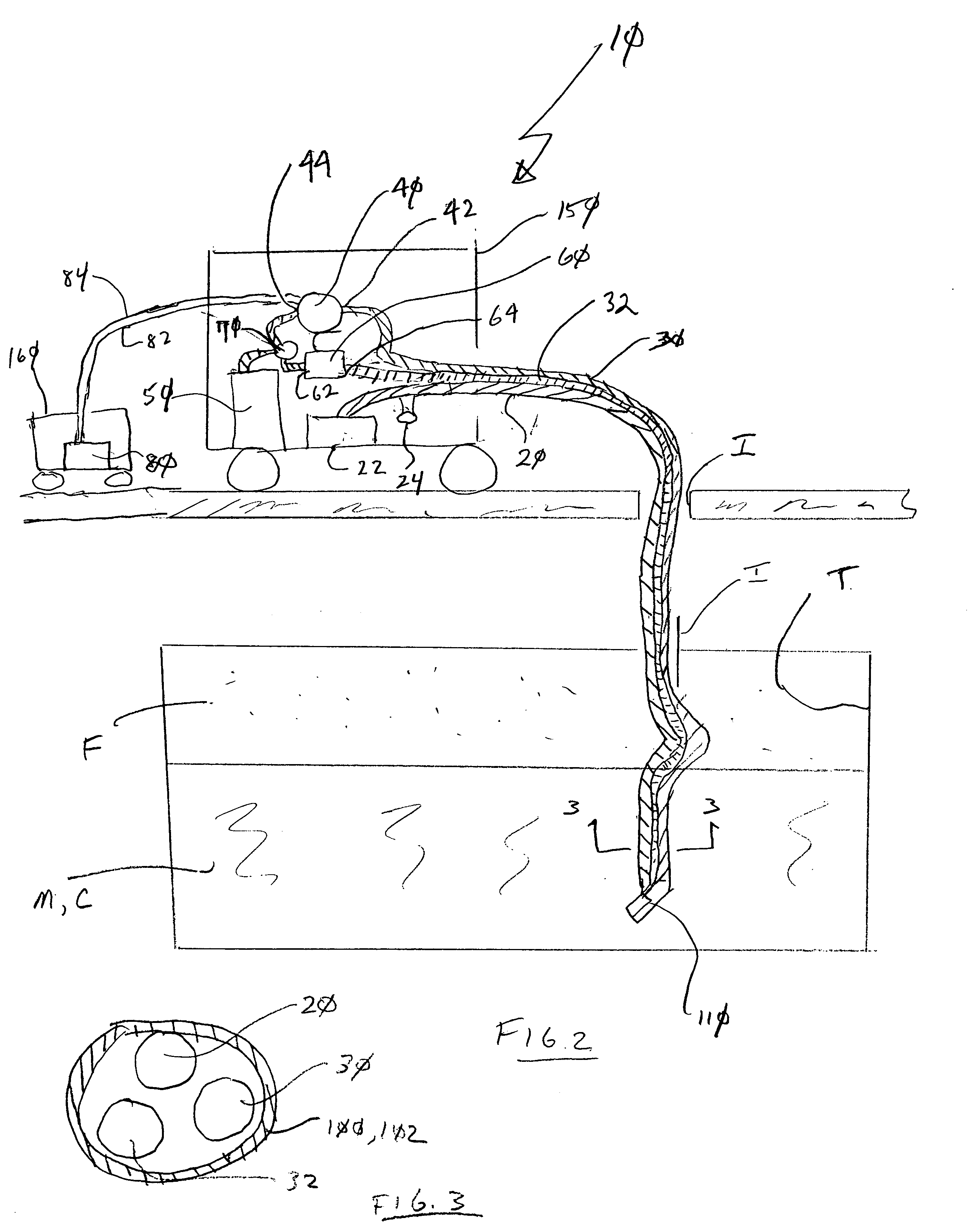
[0031] The present invention is shown in the Figures as reference numeral 10.

[0032]FIG. 2 is a block diagram of one aspect of the present invention at a high lev...


PUM

PropertyMeasurementUnit
corrosiveaaaaaaaaaa
strength propertiesaaaaaaaaaa
specific gravitiesaaaaaaaaaa

Abstract

An apparatus for detecting and removing moisture and contaminants from fuel stored in a tank includes: optical fiber for examining the fuel for moisture and contaminants, a light source and a lens; a suction hose insertable into the tank; a return hose insertable into the tank; a pump with an inlet connected to the suction hose, and an outlet; a waste holding container for receiving moisture and contaminants; a contaminant filter with an inlet and an outlet connected to the return hose; and a valve between the pump outlet, the waste holding container and the contaminant filter inlet. A method for detecting and removing moisture and contaminants from fuel stored in a tank, includes: optically inspecting fuel in the tank for moisture and contaminants; pumping fuel laden with moisture and contaminants into a measuring container until the measuring container is full; pumping the contents of the measuring container into a holding container; examining the fuel to determine whether the fuel is substantially clean of moisture and contaminants, until the fuel is substantially clean of moisture and contaminants; pumping the fuel from the tank through a contaminant filter and then back into the tank until the fuel is free of moisture and contaminants; and terminating pumping.

Description

BACKGROUND OF THE INVENTION [0001] The present application relates to an apparatus and method for removing water and other contaminants from fuel, and particularly to the use of an fiber optic cable and lens for viewing the presence of such water and contaminants. [0002] Operation and maintenance have quickly become the new buzzwords in regulatory circles. Ask any inspector about underground storage tank compliance issues and the inspector will quickly cite leak detection, cathodic protection testing, piping, sumps and under-dispenser boxes as primary concerns. Water has this nasty habit of getting into places where it does not belong. This includes sumps, dispenser boxes, basements and even tanks. Water can enter tanks by way of the infrastructure, which includes pipelines, barges or trucks. But it can also enter an underground storage tank (UST) or above ground storage tank (AST) by condensation, fill boxes or tank sumps. Of course, a tank at a retail service station is the last p...

Claims


Application Information

Patent Timeline
Patent Type & Authority Applications(United States)
IPC IPC(8): B01D35/00
CPCB67D7/76Y10S210/05B67D7/766
Inventor SUNDENG, ARILD
Owner ARILD & SHELLYS
Why Eureka
Try Eureka