Gyro-stabilized air vehicle

a technology of air vehicle and stabilizer, which is applied in the direction of vertical landing/take-off aircraft, aircraft navigation control, transportation and packaging, etc., can solve the problems of inability to land based runways, inability to use runways, and inability to provide runways, etc., to achieve the effect of improving the payload of aircra

Inactive Publication Date: 2006-10-19
BOSTAN NICOLAE
View PDF71 Cites 123 Cited by
  • Summary
  • Abstract
  • Description
  • Claims
  • Application Information

AI Technical Summary

Benefits of technology

[0030] In one embodiment, the fuselage between the two propulsion units provides a space suitable for a payload. In one embodiment, the total thrust provided by the two propulsion devices is substantially greater than a thrust from a single propulsion device that is substantially similar to each of the two propulsion devices, such that use of two propulsion devices and the fuselage allows for improved payload of the aircraft.
[0031] Yet another embodiment of the present disclosure relates to an aircraft that includes a fuselage having a longitudinal axis, and two propulsion

Problems solved by technology

In many situations, however, runways may not be available, or their use may be impractical.
For example, for military applications, land based runways are often unavailable adjacent to the operational military zone or the available runways will be occupied by larger manned fixed-wing aircraft.
Similarly, ship borne UAVs can be even further restricted in available runway space since most military ships are not equipped with sufficient deck space to

Method used


Image

  • Gyro-stabilized air vehicle
  • Gyro-stabilized air vehicle
  • Gyro-stabilized air vehicle

Examples


example embodiment

Class III-C Example Embodiment

[0079] One embodiment of a Class III-C can be similar to Class III-B except that the air vehicle has only one engine installed in the fuselage and one GS disk.

Control System and Stabilization

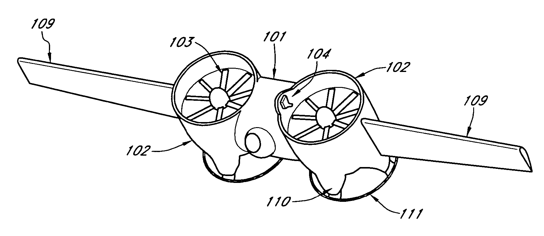
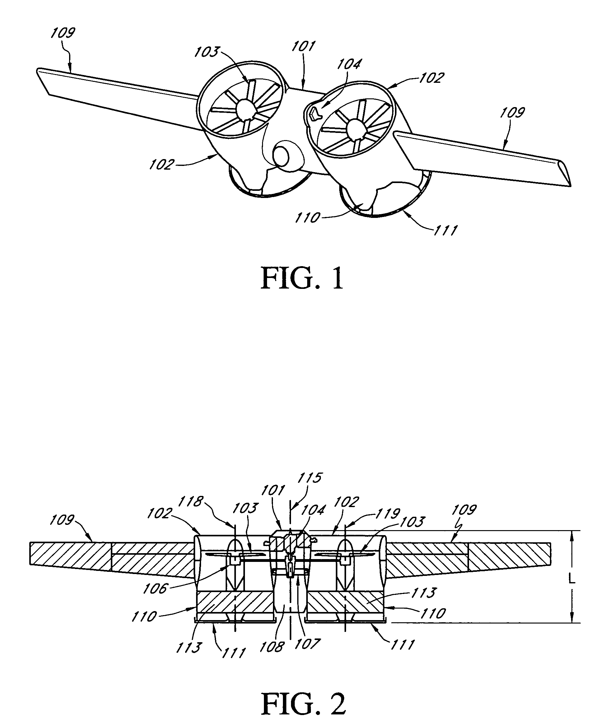
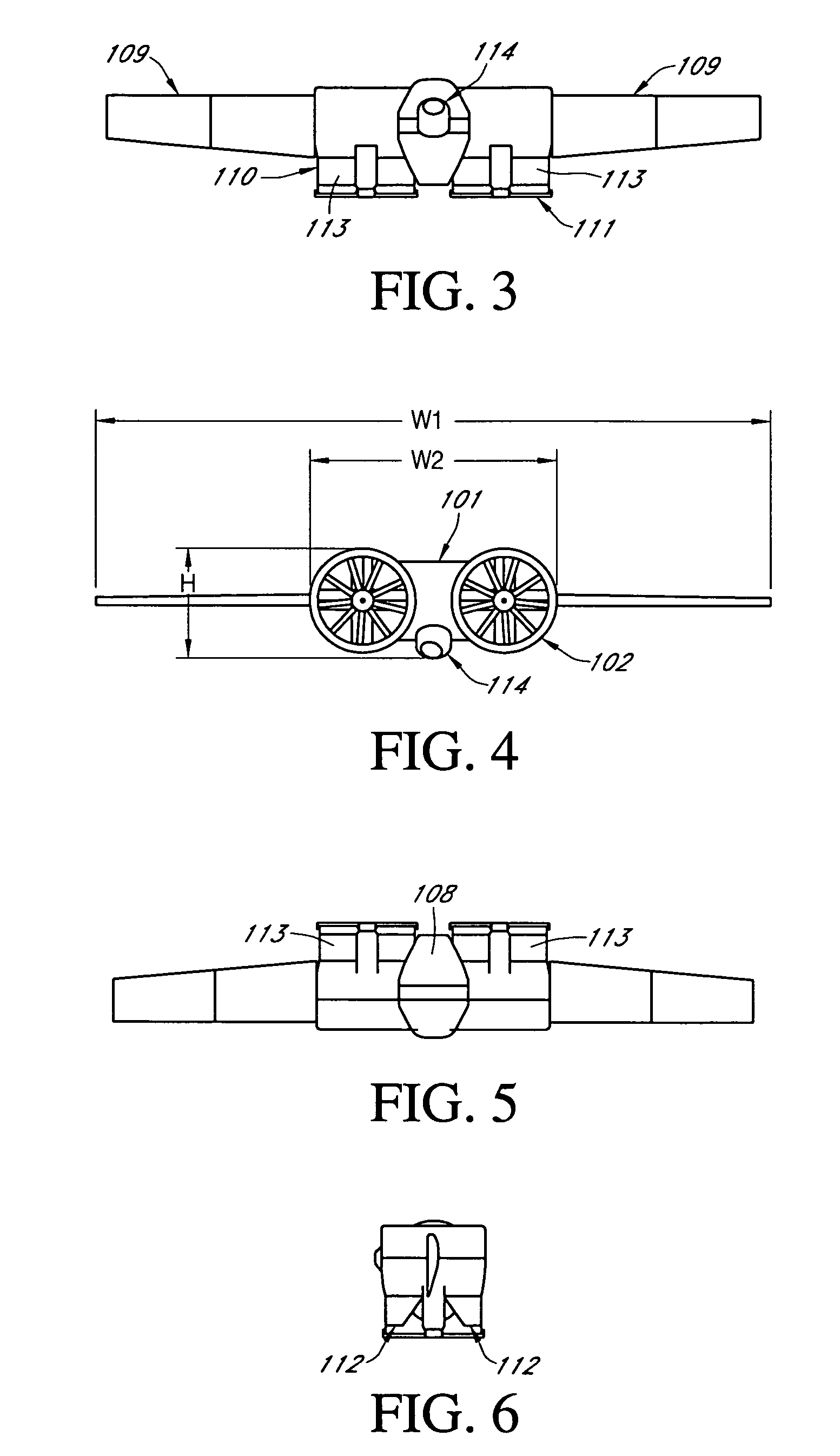
[0080] As is shown in FIGS. 1-6 and 11-18, at the rear of each shrouded propeller there can be installed two sets of control surfaces, 112 and 113 for Class II and 212 and 213 for Class III air vehicle. Preferably there are two or more control surfaces in each set. The control surfaces are pivotally mounted and are controlled by a flight control system such that by pivoting the control surfaces 112 and 113 (212 and 213) of either or both shrouds the flight operation of the air vehicles can be controlled about the pitch, yaw and roll axes. Examples of operations of the control surfaces 112 and 113 are described in greater detail below for Class II and Class III air vehicles.

[0081] As discussed above, various embodiments of the UAV incorporates a gyroscopic stabil...

example configuration

for One Embodiment of a Class III UAV

[0121] Table 2 provides a list of estimated performance characteristics for one embodiment of a Class III UAV. Other configurations are possible.

TABLE 2DescriptionCharacteristicPower plant2 × 280ccPower available for VTOL thrust2 × 25 HP = 50 HPShrouded prop inside diameter21inShrouded prop exit diameter22inShrouded prop outside diameter27inAir vehicle height (VTOL)30inAir vehicle length60inSpan (without wings)72inSpan (with wings)14ftEmpty weight (without wings)120lbWings weight10lbFuel weight (without wings)68lbFuel weight (with wings)58lbPayload weight20lbMaximum vertical takeoff weight190lbAir speed for optimized endurance60ktsAir speed for optimized range100ktsEndurance - hover at range1.5hrsEndurance - loiter (with wings)4hrsAltitude25,000ftRange125km

Example Configuration of Flight Control System

[0122]FIG. 22 shows a block diagram of one embodiment of a flight control system 700 that includes a flight control component 702. The flight c...


PUM


Abstract

A vertical takeoff and landing (VTOL) air vehicle disclosed. The air vehicle can be manned or unmanned. In one embodiment, the air vehicle includes two shrouded propellers, a fuselage and a gyroscopic stabilization disk installed in the fuselage. The gyroscopic stabilization disk can be configured to provide sufficient angular momentum, by sufficient mass and/or sufficient angular velocity, such that the air vehicle is gyroscopically stabilized during various phases of flight. In one embodiment the fuselage is fixedly attached to the shrouded propellers. In another embodiment, the shrouded propellers are pivotably mounted to the fuselage.

Description

PRIORITY CLAIM [0001] This application claims the benefit of U.S. Provisional Application No. 60 / 662,999, filed on Mar. 17, 2005, entitled “Vertical Takeoff and Landing Air Vehicle with Tilt Shrouded Propellers Gyro Stabilized by a Rotating Disk,” which is hereby incorporated by reference in its entirety.BACKGROUND [0002] 1. Field [0003] The present disclosure generally relates to aircraft technology, and in particular, relates to a manned or unmanned vertical takeoff and landing (VTOL) air vehicle that is gyroscopically stabilized to enhance controllability of flight operations. [0004] 2. Description of the Related Art [0005] Unmanned air vehicles (UAV) are vehicles that provide tremendous utility in numerous applications. For example, UAVs are commonly used by the military to provide mobile aerial observation platforms that allow for observation of ground sites at reduced risk to ground personnel. A typical UAV used in military applications, and also in other civilian type applica...

Claims


Application Information

Patent Timeline
IPC IPC(8): B64C29/00
CPCB64C3/385Y02T50/145B64C27/20B64C29/0033B64C29/02B64C39/024B64C2201/027B64C2201/042B64C2201/044B64C2201/048B64C2201/088B64C2201/104B64C2201/108B64C2201/127B64C2201/146B64C2201/162B64C2201/165B64C17/06Y02T50/10B64U50/12B64U50/11B64U70/80B64U30/10B64U10/13B64U30/20B64U50/19B64U50/14B64U50/13B64U2101/30B64U2201/20
Inventor BOSTAN, NICOLAE
Owner BOSTAN NICOLAE
Why Eureka
Try Eureka