
Railroad car coupler gap analyzer

a technology for car couplers and analyzers, which is applied in the direction of railway signalling, route devices for controlling vehicles, railway signalling and safety, etc., can solve the problems of air hose couplers, commonly referred to, being susceptible to unintended uncoupling, and disrupting normal train operation

Inactive Publication Date: 2006-10-19
PROGRESSIVE RAIL TECH
View PDF11 Cites 33 Cited by
  • Summary
  • Abstract
  • Description
  • Claims
  • Application Information

AI Technical Summary

Benefits of technology

[0033] Another aspect of the present invention is to provide a reliable machine vision algorithm to detect a low air hose.
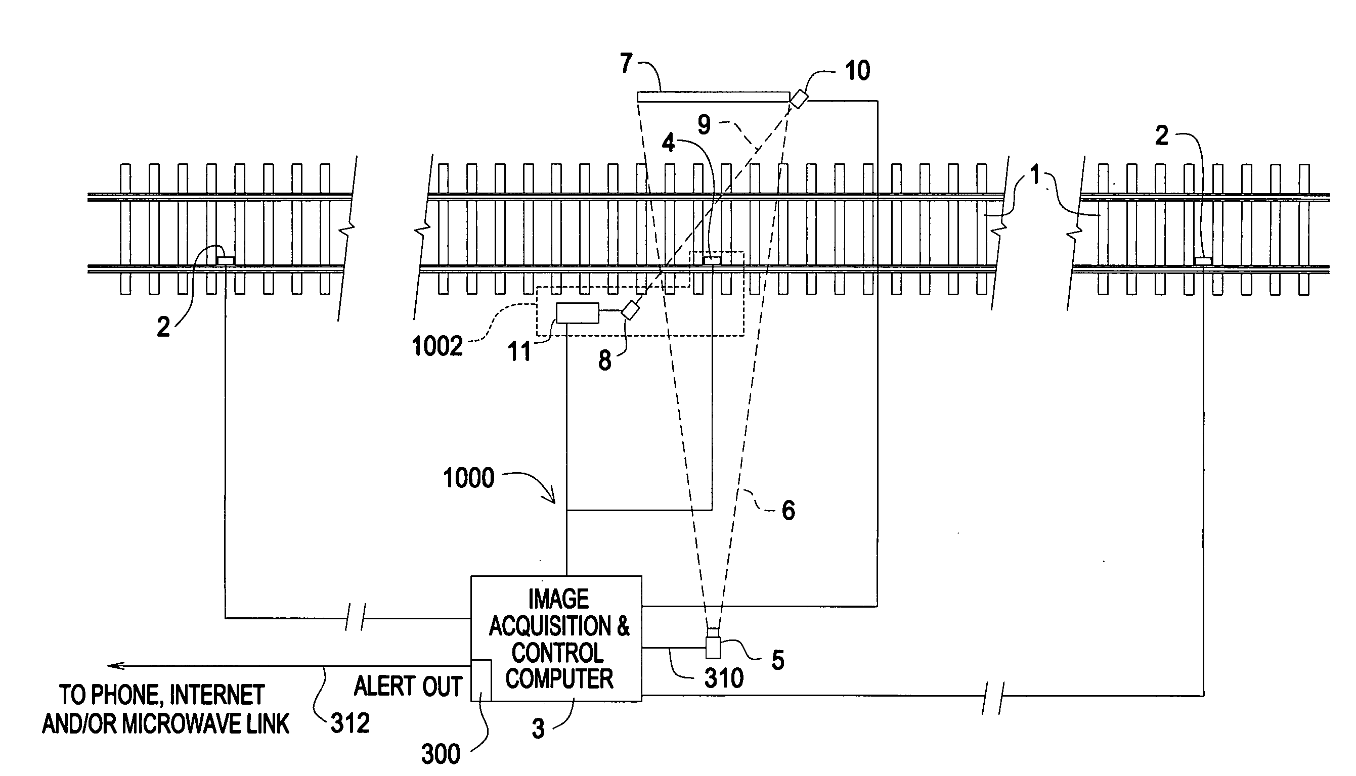
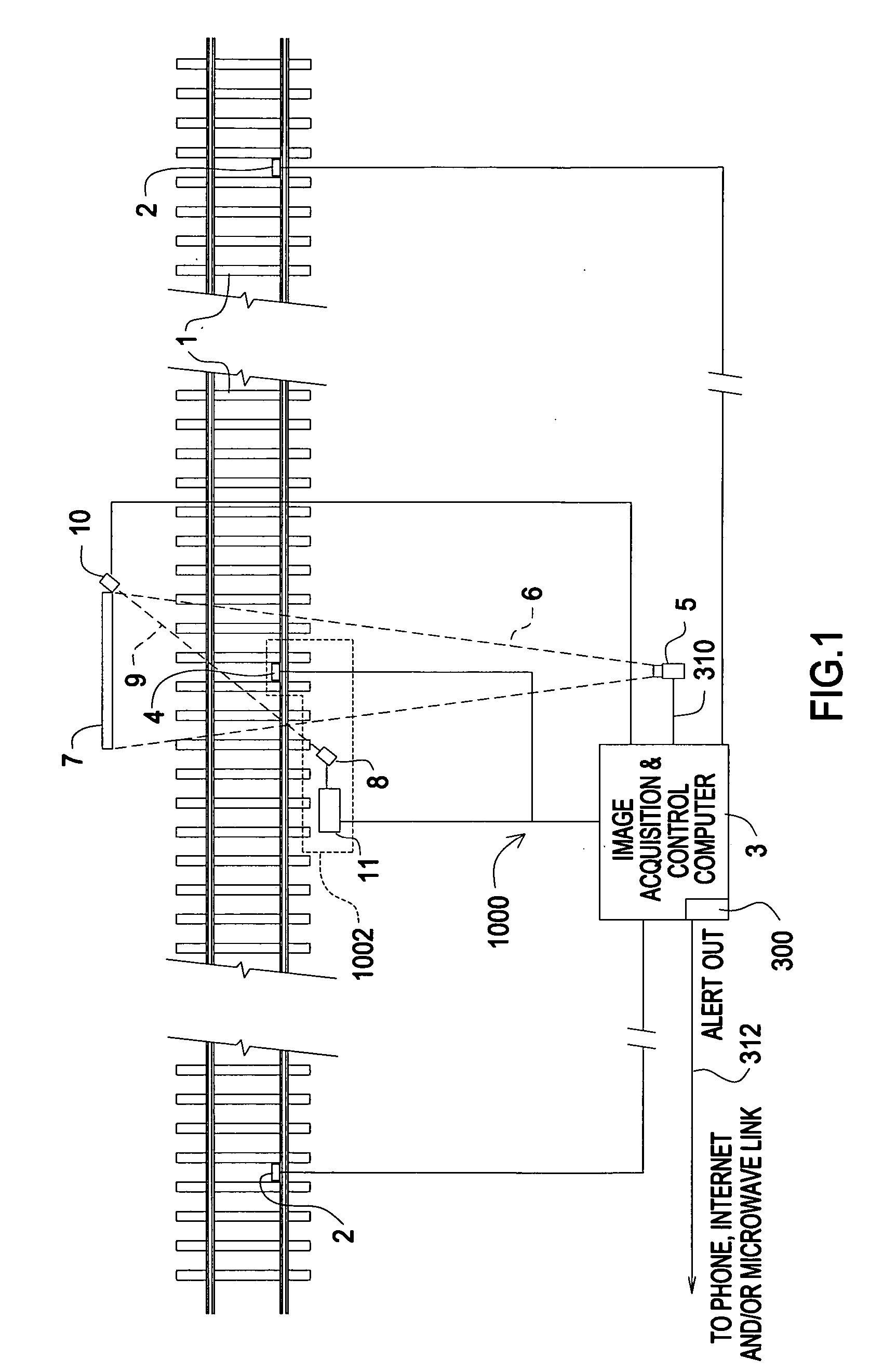
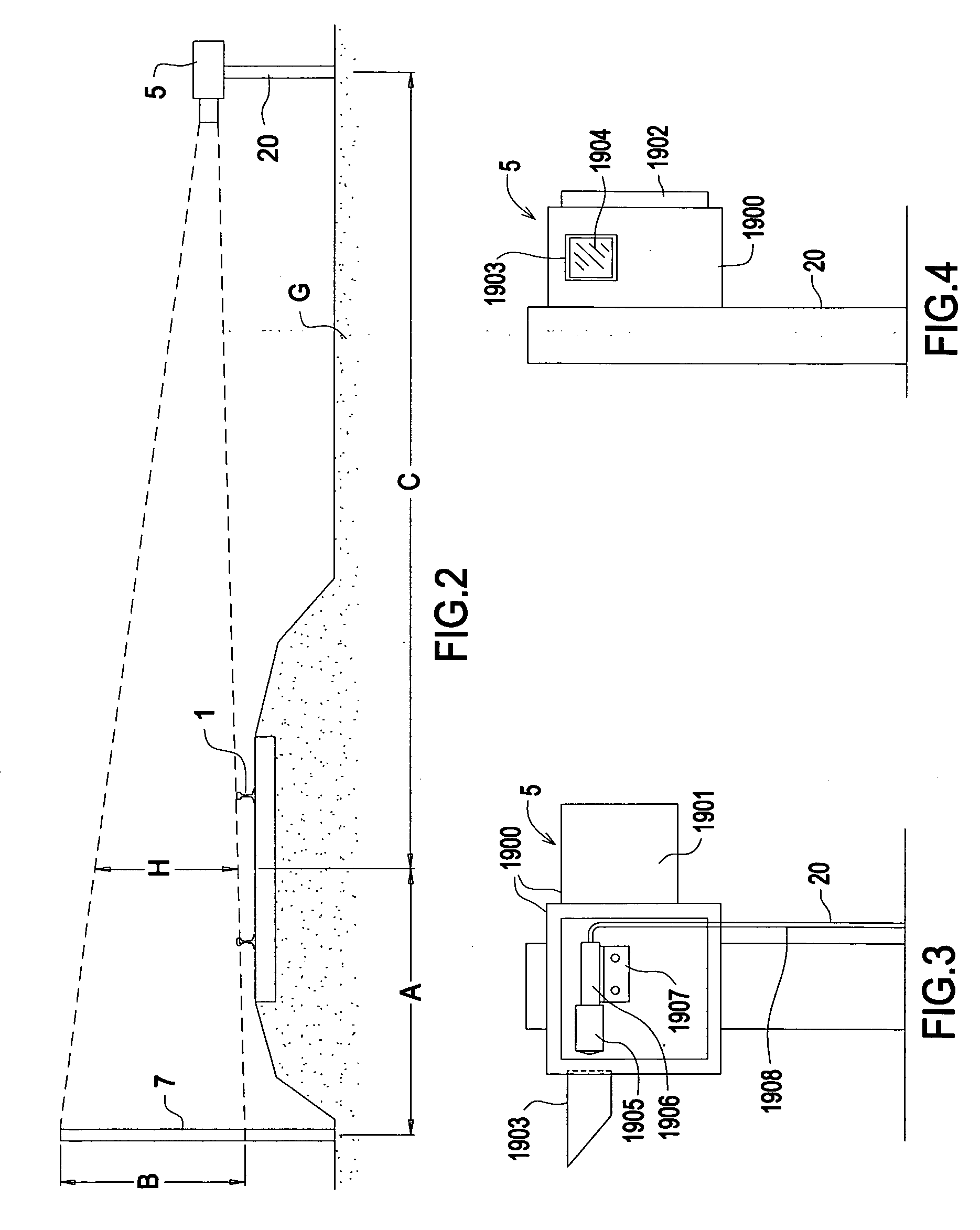
[0039] A camera resides at the side of the track and images the specific coupler gap area of a passing train. An illuminated back light panel or wall provides for consistent contrast and nighttime operation. A sophisticated camera exposure adjustment algorithm compensates for variable ambient lighting conditions. A method of signaling the camera imaging system that a coupler gap is present in the camera field of view and to acquire the current image frame is provided. A “hose finder” algorithm detects hoses in images and finds their lowest point above the top of rail. The “hose finder” algorithm discriminates against cables, straps, and other objects in coupler gap. The top of rail is automatically detected by a machine vision algorithm for hose height measurement.

Problems solved by technology

The air hose coupler, commonly referred to as the “glad hand”, is susceptible to unintended uncoupling if the air hose assembly hangs down sufficiently such that it strikes objects in the track as the train is in motion.
By design, any loss of pressure in the air brake system causes the entire train to automatically go into an emergency brake mode and come to a stop, disrupting normal train operations.
Significant mismatches between mating coupler heights have been shown to create vertical force moments that can unload a railcar's wheels and cause derailments.
These emergency braking scenarios cost railroads millions of dollars of lost revenue through down time.
Also, if the emergency braking mechanisms were to fail, then a lack of braking pressure in a train causes a dangerous situation.
Unfortunately, the dirt and grime associated with railroad coupling and braking devices would defeat this approach for detecting a low air hose.
Unfortunately, the installation and maintenance of countless radio transmitters on air hose elements would be costly and prone to failures of the radio transmitters.
The laser beam devices must be mounted across and in close proximity to the track and are subjected to severe vibrations that can cause the laser beam to deflect from the receiver, especially when railroad car wheels with flat spots pound the rails.
The housings for the laser and receiver interfere with normal track maintenance activities and may pose a trip hazard to railroad workers.
The simple beam-break approach is very poor at discriminating shapes and sizes.
The prior art only detects low hanging air hose assemblies and cannot be used for other detection tasks.

Method used


Image

  • Railroad car coupler gap analyzer
  • Railroad car coupler gap analyzer
  • Railroad car coupler gap analyzer

Examples


Embodiment Construction

[0139] The invention is composed of the components arranged as shown in FIG. 1 and consisting of:

[0140] 1. Automatic computerized image acquisition / control system (3)

[0141] 2. Charge Coupled Device (CCD) camera with lens in a weatherproof enclosure (5)

[0142] 3. Frame grabber camera interface in the data collection system (300)

[0143] 4. Camera / frame grabber electrical cable (310)

[0144] 5. Railroad car identification system (1002), comprised of a wheel detector (4) and a radio identification tag reader (11)

[0145] 6. Laser / receiver “coupler gap” detector (1001)

[0146] 7. Illuminated camera imaging back light or wall(7)

[0147] 8. Communication link (320)

Below are the preferred configurations of the camera, lens, camera imaging back light and illumination. Other configurations would work as well for different camera-to-track distances, lens focal lengths, larger back lights, etc.

[0148] 1. Camera: Electronic CCD camera with programmable electronic gain and shutter speed, ⅓″ CCD e...


PUM


Abstract

In trains a dragging air hose can snag an object on the tracks and break. A broken air hose can lead to an emergency stop or an accident caused by faulty brakes. The present invention mounts a video camera opposite a lit screen, thereby contrasting the air hose profile against a white screen in all weather and lighting conditions. Machine vision algorithms locate the air hose in a captured image from a moving train, and compute its lowest point. An alarm condition is sent to a remote location. An optional car gap detector is laser based. It helps align the car gap with the data capture for the camera. Another subsystem can include a car coupler height detection algorithm.

Description

FIELD OF INVENTION [0001] The present invention relates to using a machine vision system to scan passing railroad cars in a train in order to detect a low hanging air hose and / or coupler, thereby avoiding a broken air hose and / or uncoupling which can cause emergency braking or accidents BACKGROUND OF THE INVENTION [0002] It is common practice by railroad industries worldwide to utilize an air braking system on both passenger and freight trains. The air brake system is typically composed of a compressed air source and control valves that are normally located on the locomotives and connected through a series of pipes and hoses to the brake valves and brake actuators on each railroad car. The air supply is carried across the span between coupled railroad cars, referred to herein as the “coupler gap”, through a flexible hose / coupler arrangement 26 and 27 in FIG. 8. The air hose coupler, commonly referred to as the “glad hand”, is susceptible to unintended uncoupling if the air hose asse...

Claims


Application Information

Patent Timeline
IPC IPC(8): B61L3/00
CPCB61L23/02B61L1/16
Inventor MACE, STEPHEN E.MARTIN, ROBERT W. JR.HANDAL, STEPHEN N.
Owner PROGRESSIVE RAIL TECH
Learn More