Optical fiber systems for delivering short high power pulses

a technology of optical fiber and pulses, applied in the field of optical fiber systems, can solve the problems of inability to achieve the effect of increasing the average power of the source, inefficient multi-photo process, and high peak power,

Inactive Publication Date: 2006-10-19
FURAKAWA ELECTRIC NORTH AMERICA INC
View PDF3 Cites 68 Cited by
  • Summary
  • Abstract
  • Description
  • Claims
  • Application Information

AI Technical Summary

Benefits of technology

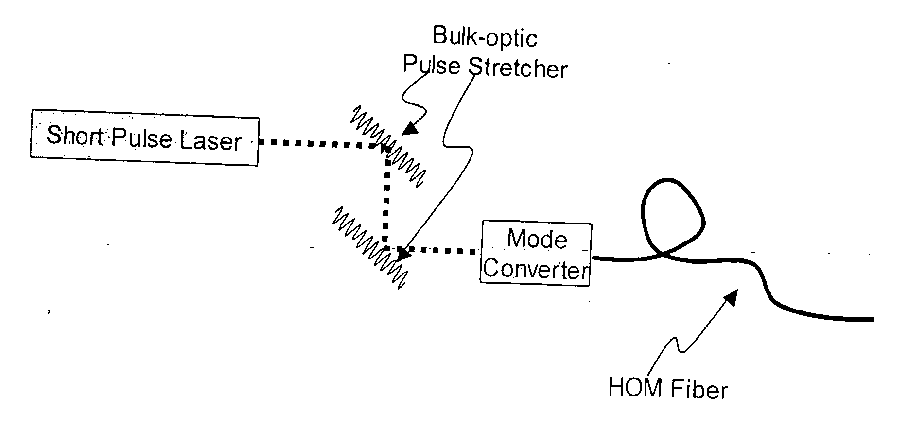
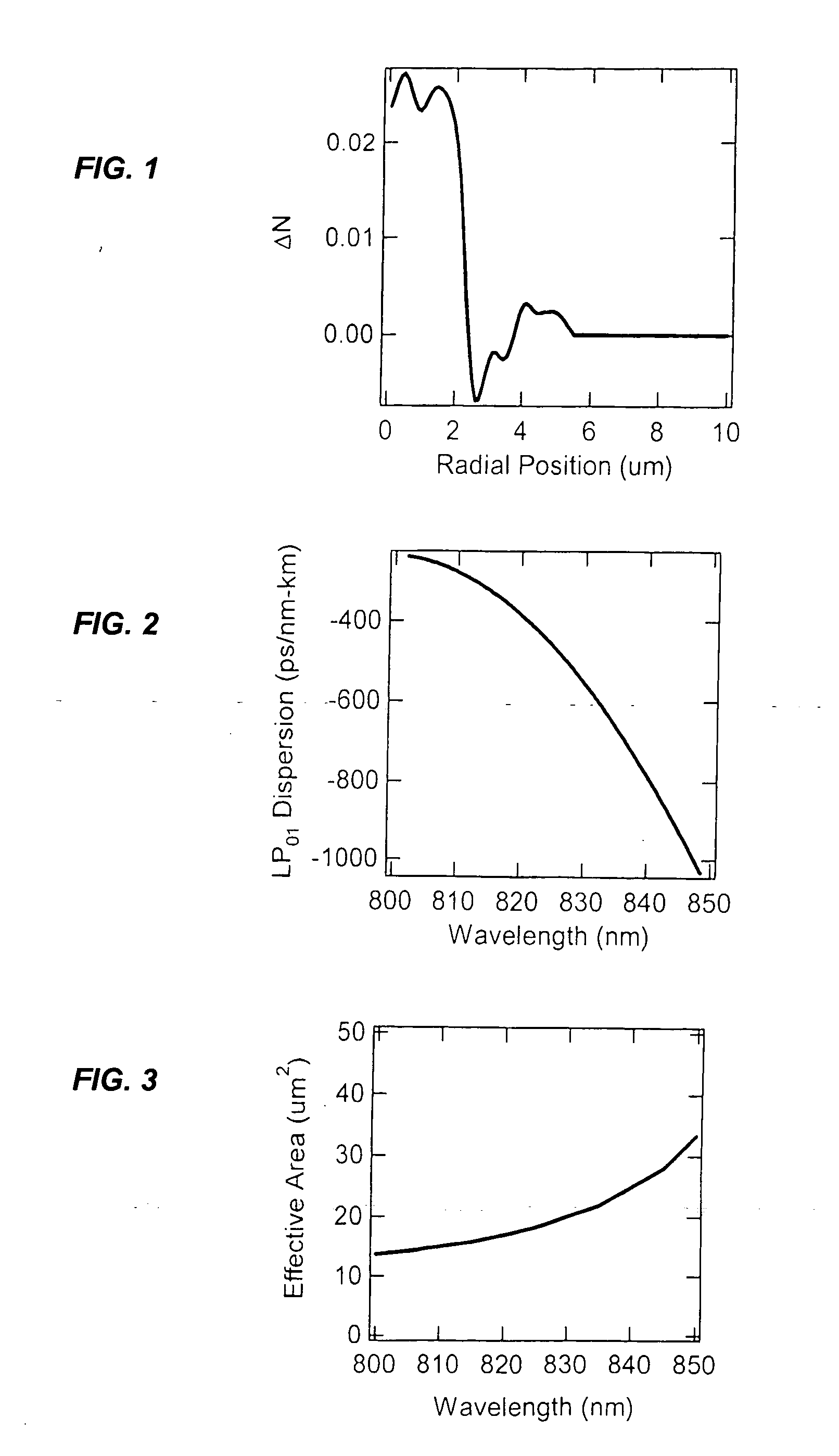
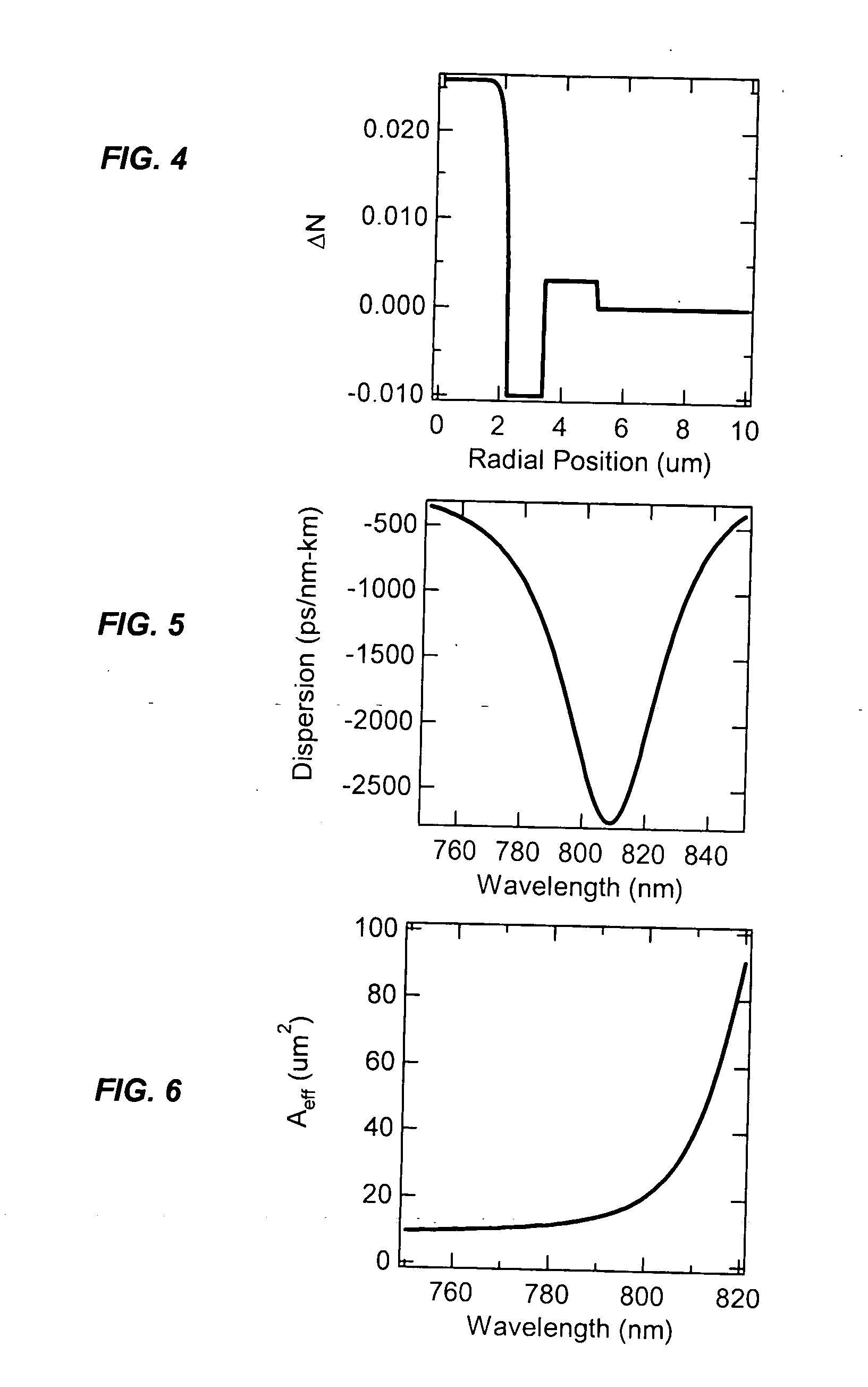
[0015] We have developed an optical fiber system for delivering ultrashort pulses with minimal distortions due to nonlinearity. The system is based on delivering the optical pulses in a higher order mode (HOM) of a few-moded fiber. The fiber is designed so that the dispersion for the HOM is very large. This results in a dispersion length LD for the delivery fiber that is exceptionally small, preferably less than the non-linear length LNL. Under these conditions the optical pulses experience minimum non-linear impairment, and short pulse / high peak power levels are reproduced at the output of the delivery fiber.

Problems solved by technology

Since multi-photo processes are by nature inefficient, high peak powers are needed.
However, this cannot be achieved by increasing the average power of the source, because high average power will cause tissue damage.
However, there are two physical constraints that affect the output from the delivery fiber.
In addition, since the peak power levels are so high, nonlinear phase shifts due self-phase modulation (SPM) lead to a narrowing of the spectral width of the pulse, further broadening the pulse.
Accordingly, while the dispersion problem may be addressed with some effectiveness, the nonlinear SPM effect is non-recoverable.
Propagation in multiple modes degrades the ability to tightly focus the output from the fiber.
Propagation in multiple modes also spreads the pulses due to modal dispersion, which lowers the peak power and reduces the efficiency of nonlinear measurement techniques.
This fiber satisfies all the above criteria, but at pulse energies >0.1 nJ, SPM severely distorts the pulse.
However, pulse widths obtained with this method are still undesirably large, especially for two-photon applications.
However, it appears that coupling effectively only into the fundamental mode in microstructured fibers is a problem, and significant power is lost to higher order modes.
This causes unwanted modal noise in the system.
In addition, microstructured fibers have poor geometric control compared to standard doped fibers, and a potential drawback is geometric ovalities that would cause large polarization mode dispersion (PMD), a source of additional noise.
However, photonic bandgap fibers are difficult to manufacture in comparison to doped fibers, and hence are not a cost-effective solution.
Geometric regularity problems are severely exacerbated, leading to the possibility of high PMD and associated problems.
They also suffer from the inability to splice a mode-shaping element at the fiber output, because the splice causes the photonic bandgap effect to disappear, and will yield large losses.
While this produces short pulses, the power levels are low and not desirable for two-photon applications.

Method used


Image

  • Optical fiber systems for delivering short high power pulses
  • Optical fiber systems for delivering short high power pulses
  • Optical fiber systems for delivering short high power pulses

Examples


Embodiment Construction

[0026] The relative magnitudes of dispersive and nonlinear effects in fibers used for short pulse propagation are succinctly described by two characteristic lengths, the dispersion length LD, and the nonlinear length LNL, given by: LD=(τ2D)·(-2⁢π⁢ ⁢cλ2)⁢⁢LNL=c⁢ ⁢Aeffn2⁢ωpeak(1)

where τ is the undistorted pulsewidth, β2 is the dispersion of the fiber waveguide, c is the speed of light, ω is the central frequency of the pulse, n2 is the nonlinear response of the fiber material, Ppeak is the peak power of the pulse in the fiber, Aeff is its effective area, and λ is the central wavelength of the pulse. These characteristic lengths describe the maximum distance a pulse can travel before it becomes significantly distorted by the corresponding impairment. Since dispersion can be easily compensated but SPM cannot, it is desirable to design a fiber such that LD is as small as possible in comparison to LNL. In this case, a highly chirped pulse can be launched into a fiber so that it is compr...


PUM


Abstract

Described is an optical fiber system for delivering ultrashort pulses with minimal distortions due to nonlinearity. The system is based on delivering the optical pulses in a higher order mode (HOM) of a few-moded fiber. The fiber is designed so that the dispersion for the HOM is very large. This results in a dispersion length LD for the delivery fiber that is exceptionally small, preferably less than the non-linear length LNL. Under these conditions the system may be designed so the optical pulses experience minimum non-linear impairment, and short pulse / high peak power levels are reproduced at the output of the delivery fiber.

Description

FIELD OF THE INVENTION [0001] This invention relates to optical fiber systems that produce very short, high power, optical pulses. BACKGROUND OF THE INVENTION [0002] (Parts of the following section may not be prior art.) [0003] Optical fiber lasers are available that produce optical pulses with high pulse energy, good beam quality and excellent optical characteristics. Several applications for these optical pulse lasers exist, ranging from time-resolved near-field scanning optical microscopy (NSOM) pump-probe experiments for understanding ultrafast electronic processes in materials (see S. Smith, N. C. R. Holme, B. Orr, R. Kopelman and T. B. Norris, “Ultrafast measurement in GaAs thin films using NSOM,”Ultramicroscopy, vol. 71, pp. 213-223, 1998); for two-photon fluorescence of dyes (see A. Lago, A. T. Obeidat, A. E. Kaplan, J. B. Khurgin, P. L. Shkilnikov and M. D. Stern, “Two-photon-induced fluorescence of biological markers based on optical fiber,”Optics Letters, vol. 20, pp. 205...

Claims


Application Information

Patent Timeline
Patent Type & Authority Applications(United States)
IPC IPC(8): H04B10/12
CPCG02B6/02023G02B6/03644G02B6/02214H04B10/25H04B10/2507H04B10/2525
Inventor RAMACHANDRAN, SIDDHARTHWIELANDY, STEPHAN
Owner FURAKAWA ELECTRIC NORTH AMERICA INC
Why Eureka
Try Eureka