Line system for fluids having volatile components

a technology of volatile components and fluids, which is applied in the direction of liquid fuel feeders, braking systems, machines/engines, etc., can solve the problems of complex multi-layer structure of lines, expensive polymers, and difficulty in producing good adhesion of different types of polymer layers, and achieves the effect of simple production

Active Publication Date: 2006-10-26
EMS CHEM AG
View PDF4 Cites 45 Cited by
  • Summary
  • Abstract
  • Description
  • Claims
  • Application Information

AI Technical Summary

Benefits of technology

[0015] The object of the present invention is to suggest an alternative line system for fluids having volatile components, which is simple to produce and wh

Problems solved by technology

An essential disadvantage of the fuel line systems known from the related art is the often complex multilayer structure of the lines used, sometimes having costly polymers.
In addition, the difficulty exists of producing good adhesion of different types of polymer layers with one another (often using adhesion promoting layers), in order to prevent delamination of the polymer layers.
In spite of using such barrier layers, however, fuel permeation through the walls of the plastic pipes used cannot be prevented completely, because a diffusion, if only a very slight, of hydrocarbon molecules through the pipe wall always occurs with the barrier plastics.
In addition, when the

Method used


Image

  • Line system for fluids having volatile components
  • Line system for fluids having volatile components
  • Line system for fluids having volatile components

Examples


first embodiment

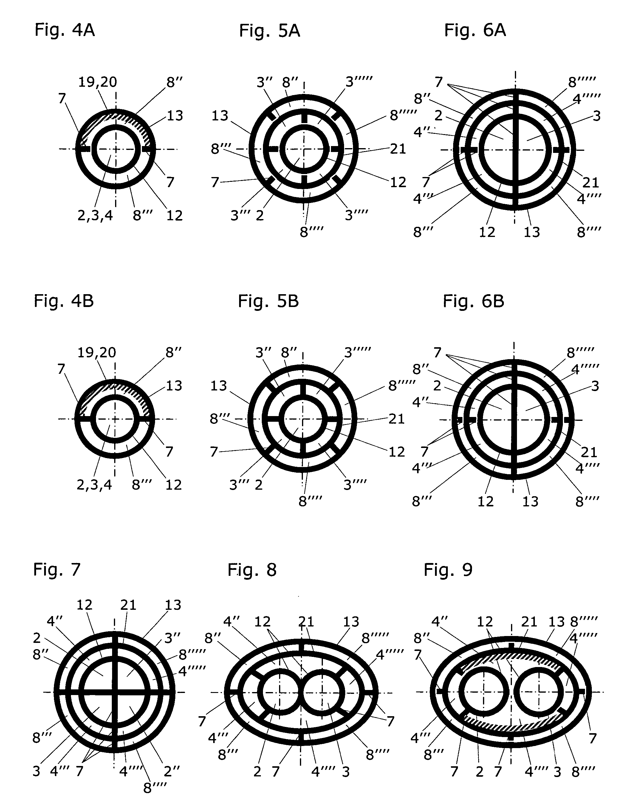
[0039]FIG. 4 shows a cross-section through the simplest, first embodiment of a line system 1 according to the present invention, which is implemented at least over the section A as a plastic hollow profile and comprises a scavenging line 8, which is enclosed by a second line wall 13. This scavenging line 8 comprises two scavenging chambers 8″, 8′″ here, which are separated from one another by support webs 7. The totality of these scavenging chambers 8″, 8′″ essentially encloses the fluid line 2,3,4. If one views the volume of the support webs 7 as belonging to the volume of the scavenging line 8, and particularly if (as shown in FIG. 4A) the first line wall 12 is separated from the support webs 7, the scavenging line 8 completely encloses the fluid line 2,3,4. This separation of the support webs 7 from the first line wall 12 is particularly preferred if greater flexibility of the plastic hollow profile is desired, for example, for thermoforming or laying on an automobile. Instead of...

second embodiment

[0044]FIG. 5 shows a cross-section through the flow and return lines of a line system according to the present invention, according to a This is a line system 1 for fluids having volatile components, which comprises at least one fluid line (a flow line and a return line 2,3 here), each having a separate inlet 10 and outlet 11. These fluid lines 2,3 are enclosed by a first line wall 12 and extend—close-fitting to one another—jointly over a section A of the line system 1. The two fluid lines 2,3 are separated from one another at least by the first line wall 12 over their entire length. The two fluid lines 2,3 are enveloped by an intermediate wall 21. The cross-section shows that the line system 1 is implemented at least over the section A as a plastic hollow profile and comprises a scavenging line 8 situated around the intermediate wall 21. This scavenging line 8 is enclosed by a second line wall 13 and comprises one or more (four here) scavenging chambers 8″, 8′″, 8″″, 8′″″, which a...

third embodiment

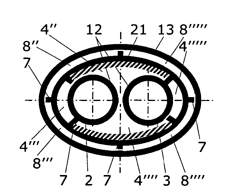
[0045]FIG. 6 shows a cross-section through the flow, return, and ventilation lines of a line system according to the present invention, according to a In contrast to FIG. 5, here a ventilation line 4 is additionally situated concentrically, i.e., coaxially to the two fluid lines jointly forming a circular cross-section with the first wall 12. These fluid lines are identified here as the flow line 2 and as the return line 3 and are separated from one another by a support web 7. A ventilation line 4, comprising four line chambers 4″,4′″, 4″″, 4′″″, is situated around these fluid lines 2,3 and is delimited using an intermediate wall 21. All fluid lines 2,3,4 of the line system 1, which is implemented as a plastic hollow profile at least over the section A and comprises a scavenging line 8, are essentially enclosed by the scavenging line 8 and / or its scavenging chambers 8″,8′″,8″″, 8′″″, which are separated from one another by support webs 7. As shown in FIG. 6A, the first line wall 12...


PUM


Abstract

A line system (1) for fluids having volatile components, which comprises at least one fluid line (2,3,4), each having a separate inlet (10) and outlet (11), the fluid lines (2,3,4) being enclosed by a first line wall (12) and extending jointly over a section (A) of the line system (1) close-fitting to one another, but being separated from one another at least by the first line wall (12) over the entire length of the fluid lines (2,3,4). The line system (1) is implemented as a plastic hollow profile at least over the section (A) and comprises a further fluid line (8), which is enclosed by a second line wall (13), and comprises one or more line chambers (8″,8′″), which are at least partially separated from one another by support webs (7), whose totality at least essentially encloses the fluid lines (2,3,4). In addition, the first and second line walls (12,13) and the support webs (7) of the plastic hollow profile being implemented from the same polymer material. The line system (1) according to the present invention is characterized in that the further fluid line (8) is implemented as a scavenging line (8) having scavenging chambers (8″,8′″) and is connected to a scavenging device, which is implemented for flushing or suctioning the scavenging line (8) and therefore for conveying away and collecting permeates originating from the fluid lines.

Description

RELATED APPLICATIONS [0001] This patent application claims priority of the Swiss patent application No. CH 2005 00582 / 05 filed on Mar. 24, 2005. FIELD OF TECHNOLOGY [0002] According to a first aspect, according to the preamble of claim 1, the present invention relates to a line system for fluids having volatile components, which comprises at least one fluid line having a separate inlet and outlet, the fluid lines being enclosed by a first line wall and extending jointly over a section A of the line system close-fitting to one another, but being separated from one another over the entire length of the fluid lines at least by the first line wall, the line system being implemented at least over the section A as a plastic hollow profile and comprising a further fluid line, which is enclosed by a second line wall and comprises one or more line chambers at least partially separated from one another by support webs, whose totality essentially encloses the fluid lines, and the first and sec...

Claims


Application Information

Patent Timeline
IPC IPC(8): F16L9/18F02M55/02
CPCB60K15/01B60K15/03504F02M37/0017F02M37/20F16L9/19F02M61/166F02M2200/9015F02M2200/9038F02M55/00B61H13/20B61H5/00B60T7/128B60T7/22B60Y2200/30
Inventor STOLARZ, ALEXKETTL, RALPHSTURZEL, ANDRE
Owner EMS CHEM AG
Why Eureka
Try Eureka