Transilluminator with ultraviolet light emitting diode array

Inactive Publication Date: 2006-10-26
WALUSZKO ALEX
View PDF2 Cites 57 Cited by
  • Summary
  • Abstract
  • Description
  • Claims
  • Application Information

AI Technical Summary

Benefits of technology

[0023] Another object of the invention is to provide a method and apparatus in which sequential analysis of several samples is greatly simplified and is substantially more accurate than is possible with prior art transilluminators because of the minimal effect on excitation intensity of s

Problems solved by technology

This configuration limits the actual viewing of the fluorescent labeled sample by the researcher in real-time.
Accordingly, in virtually all wa

Method used


Image

  • Transilluminator with ultraviolet light emitting diode array
  • Transilluminator with ultraviolet light emitting diode array
  • Transilluminator with ultraviolet light emitting diode array

Examples


Example

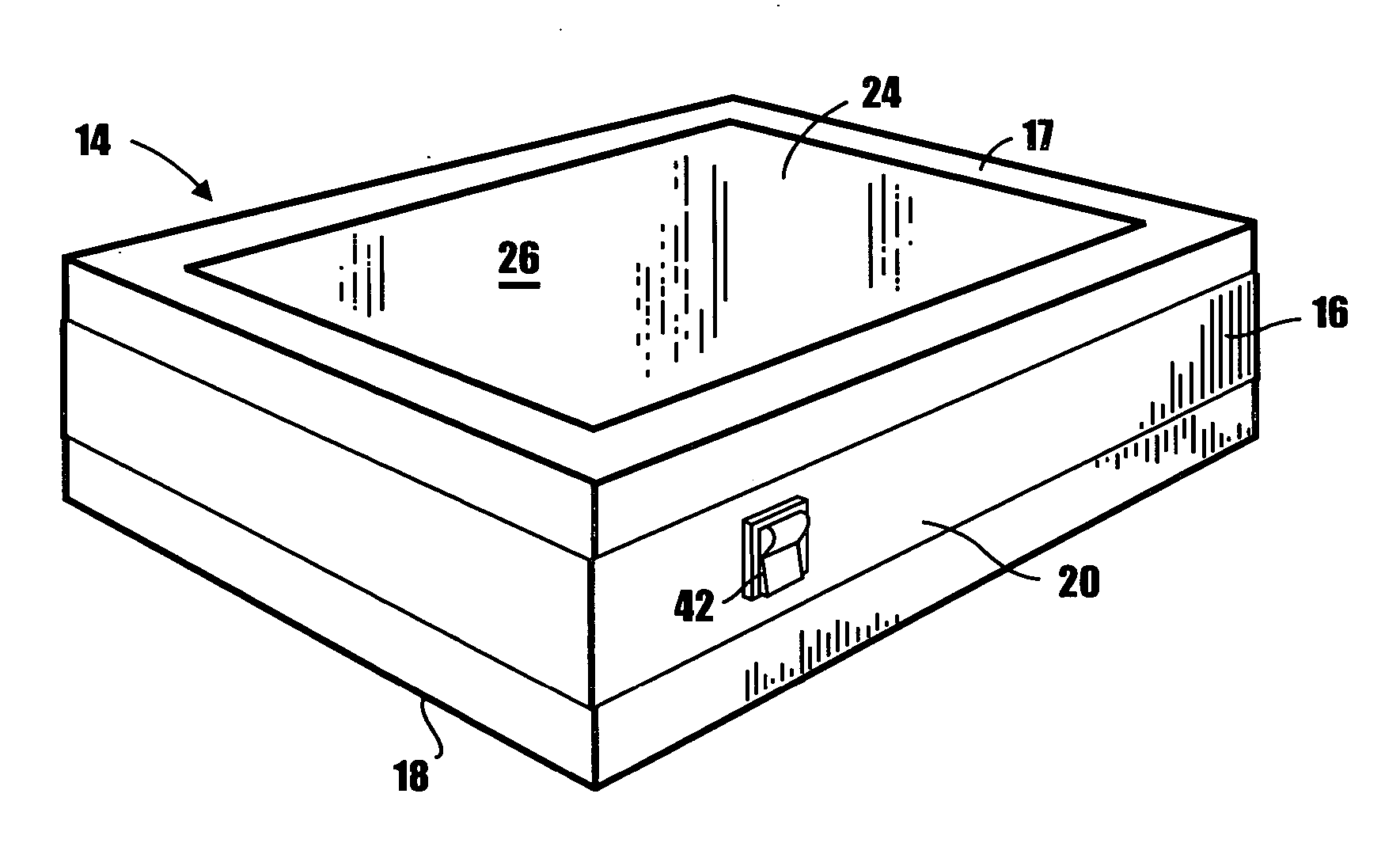
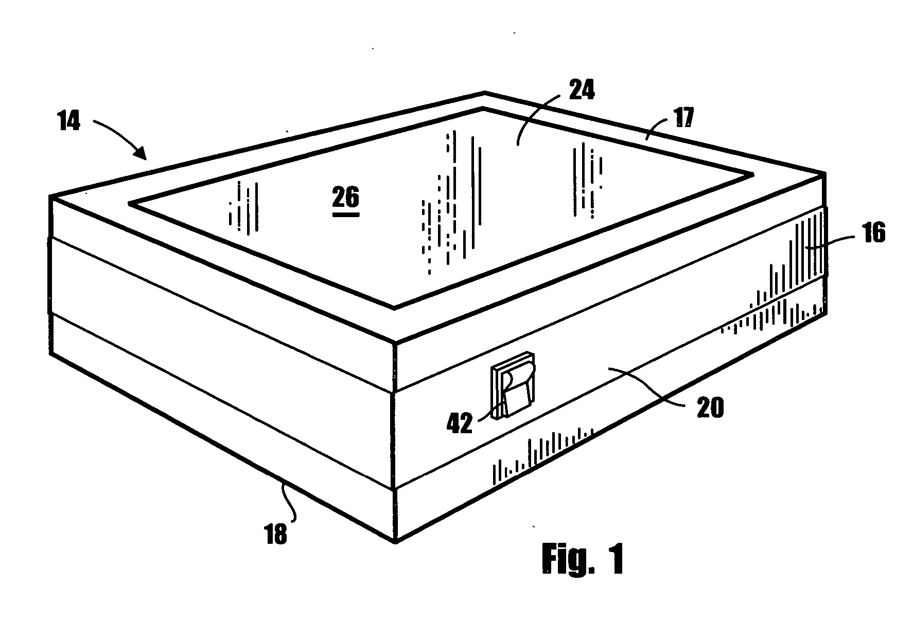
[0031] Referring to the drawings and particularly to FIG. 1, one embodiment of the apparatus of the invention for uniformly illuminating molecular samples with ultraviolet radiation is there shown and generally designated by the numeral 14. The apparatus of this form of the invention comprises a housing 16 having interconnected top, bottom and sidewalls 17, 18, and 20 respectively that define an internal chamber 22 (FIG. 2). Carried by top wall 17 is a sample supporting surface or area 26.

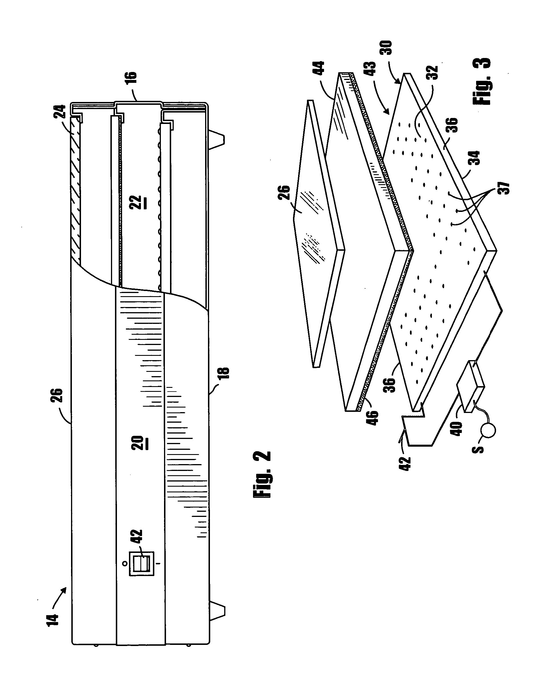
[0032] An important aspect of the apparatus of the present invention comprises irradiation means disposed within chamber 22 for uniformly irradiating the sample supporting area with ultraviolet light at a first wavelength. This novel irradiation means here comprises a base 30 having interconnected top, bottom and side walls 32, 34 and 36 respectively. Mounted on the top wall 32 of base 30 is a multiplicity of spaced-apart ultraviolet light emitting diodes 37. Also forming a part of the novel radia...


PUM


Abstract

A method and apparatus for genomic or proteomic research to visualize fluorescent labeled DNA, RNA or protein samples that have been separated for documentation and analysis. The apparatus includes a novel radiation source for uniformly irradiating the samples which comprises an array of UV LEDS. In one form of the invention the apparatus also includes a first conversion plate that is carried by the housing at a location intermediate the radiation source and the sample supporting platform for converting the radiation emitted from the source to radiation at a second wavelength.

Description

BACKGROUND OF THE INVENTION [0001] This is a Continuation-in-Part application of a co-pending application U.S. Ser. No. 10 / 842,909 filed May 10, 2004.FIELD OF THE INVENTION [0002] The present invention relates generally to ultraviolet radiation devices. More particularly, the invention concerns an apparatus for use in genomic or proteomic research to visualize fluorescent labeled DNA, RNA or protein samples that have been separated for documentation and analysis. DISCUSSION OF THE PRIOR ART [0003] By way of brief background, ultraviolet (UV) light, which is electromagnetic radiation in the region of the spectrum located between X-rays and visible light, is typically divided into three principal ranges, namely long wave, mid-range, and short wave. For each of these UV ranges specific applications have been developed. [0004] As a general rule, the desired ultraviolet wavelength is obtained from a fluorescent-style tube that is an electric discharge device that uses a low-pressure merc...

Claims


Application Information

Patent Timeline
IPC IPC(8): G01J1/42G01N21/33G01N21/64
CPCG01N21/33G01N2201/0626G01N21/645G01N21/6428G01J1/58G01J3/10G01N21/6447
Inventor WALUSZKO, ALEX
Owner WALUSZKO ALEX
Why Eureka
Try Eureka