Power driving circuit for controlling a variable load ultrasonic transducer

a transducer and variable load technology, applied in the field of ultrasonic systems, can solve the problems of limiting the operating frequency of the electrical system, limiting the power level of the scr system, and not allowing the effective control of the ultrasonic prob

Inactive Publication Date: 2006-10-26
SULPHCO
View PDF7 Cites 47 Cited by
  • Summary
  • Abstract
  • Description
  • Claims
  • Application Information

AI Technical Summary

Benefits of technology

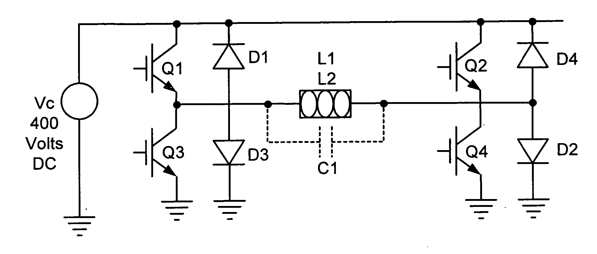
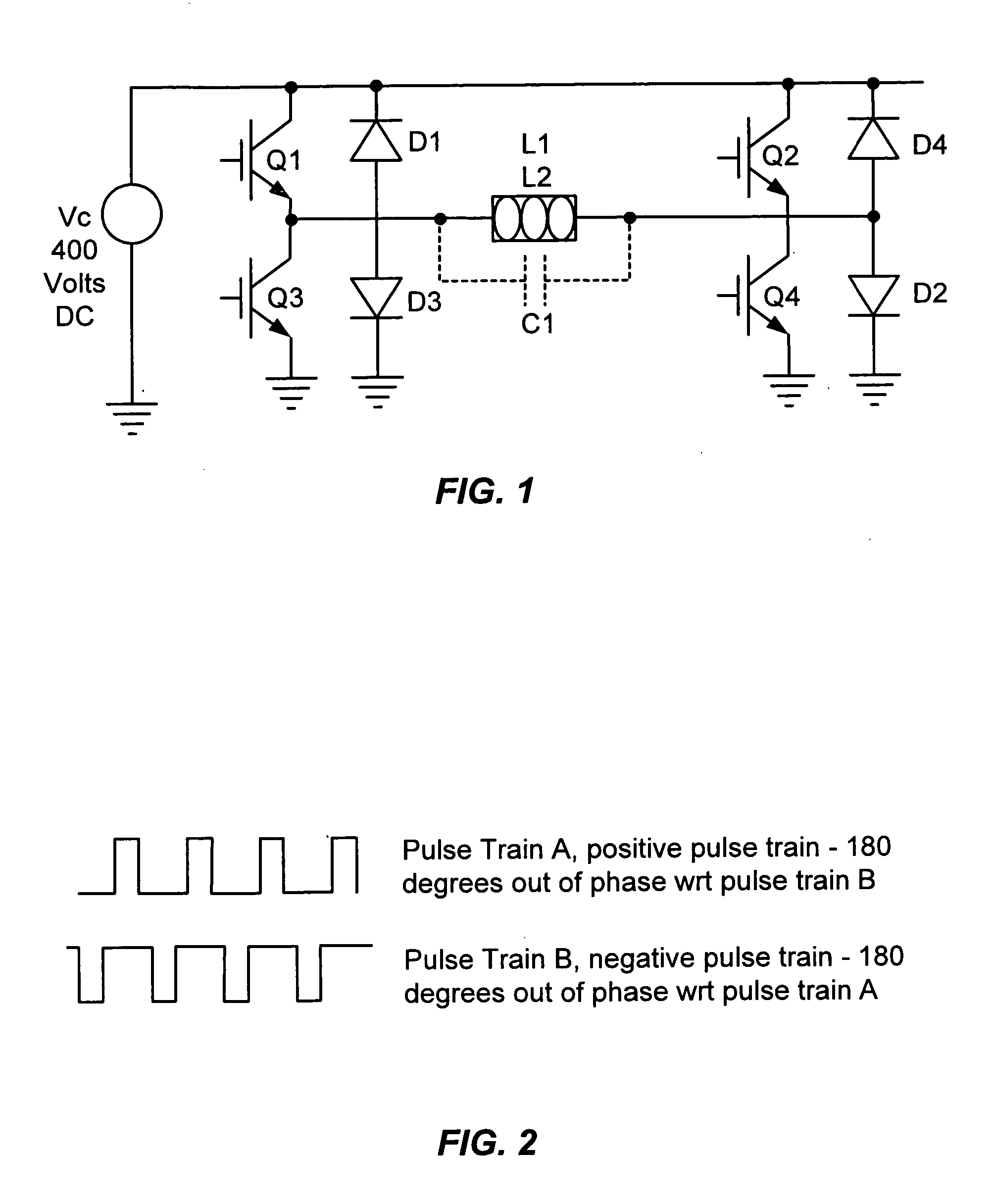
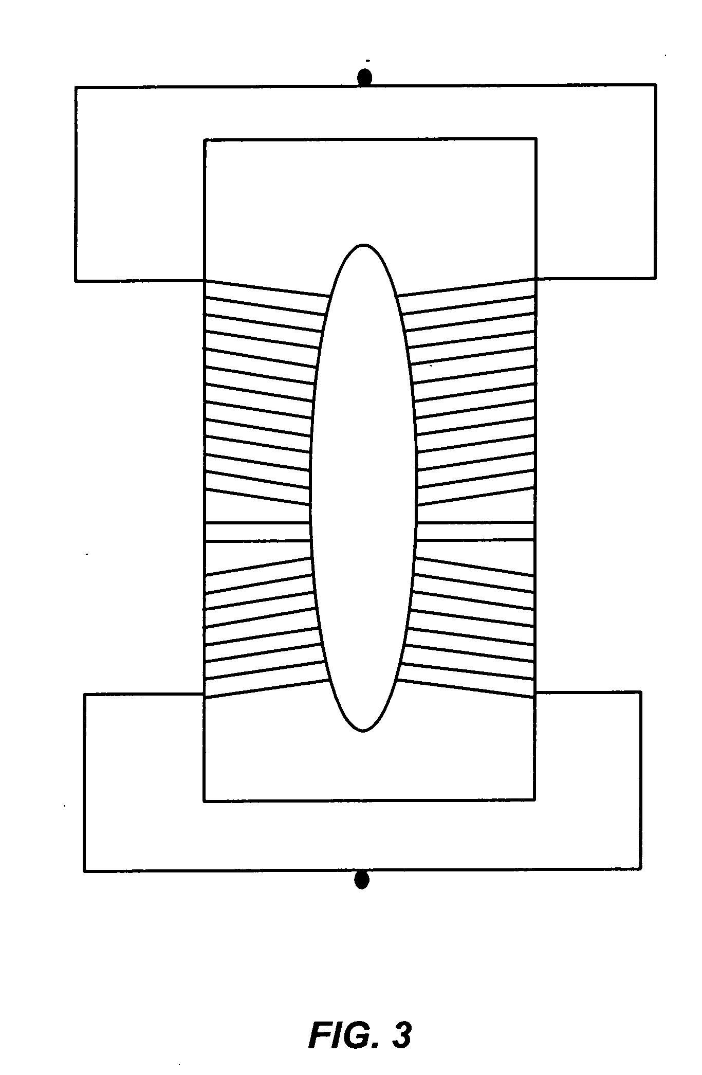
[0008] In one aspect, the embodiments of the present invention are directed to a high-powered (e.g., >500 W) ultrasonic generator for delivering high-power ultrasonic energy to a varying load. In one embodiment, the ultrasonic generator includes a variable frequency triangular waveform generator coupled with a pulse width modulator. The output from the pulse width modulator is coupled with the gates of an IGBT, which amplifies the signal and delivers it to a coil that is used to drive a magnetostrictive transducer. In one embodiment, high voltage of 0-600 VDC is delivered across the collector and emitter of the IGBT after the signal is delivered. The output of the IGBT is then a square waveform with a voltage of ±600V. This voltage is sent to a coil wound around the ultrasonic transducer. The voltage creates a magnetic field on the transducer and the magnetostrictive properties of the transducer cause the transducer to vibrate as a result of the magnetic field. The use of the IGBT as the amplifying device obviates the need for a SCR circuit, which is typically used in low powered ultrasonic transducers, and which would get overheated and fail in such a high-powered and load-varying application.

Problems solved by technology

Typically, SCR's require a forced turn off system having a particular capacitor value to control and turn off the SCR which in turn limits the operating frequency of the electrical system.
Also, the SCR systems are limited to much lower power levels which do not allow for the effective control of an ultrasonic probe at higher power levels.
However, an SCR-based ultrasonic generator when used in a process which exposes an attached ultrasonic probe to varying load conditions, such as the processing of liquid hydrocarbons, limits the effectiveness of the probe in different liquids.
This limited effectiveness is due to the loading effect different liquids will have on the ultrasonic probe.

Method used


Image

  • Power driving circuit for controlling a variable load ultrasonic transducer
  • Power driving circuit for controlling a variable load ultrasonic transducer
  • Power driving circuit for controlling a variable load ultrasonic transducer

Examples


Embodiment Construction

[0015] Prior to the invention of the present ultrasonic generator, the prior art ultrasonic generators relied on Silicon Controlled Rectifier (“SCR”) technology. In these generators, the SCRs pulse current through an ultrasonic probe at a frequency of about 17.5 kHz. At this fast switching frequency, the SCRs can easily become overheated and fail. To address this overheating problem, the SCRs require a forced turn off system commonly know in the field of power electronics as “Forced Commutation.” This means that when a signal is delivered to the system to turn on the SCR, it will remain on for a specified amount of time after that signal is turned off. It is possible through forced commutation to make the SCR turn off faster. This forced commutation is required for a faster switching frequency of 17.5 kHz. Often due to this process the SCR becomes weakened and fails. Another problem with the SCR systems is that a specific capacitor arrangement is needed in order to make the forced c...


PUM


Abstract

The present invention is directed to a high-powered (e.g., >500 W) ultrasonic generator for use especially for delivering high-power ultrasonic energy to a varying load including compressible fluids. The generator includes a variable frequency triangular waveform generator coupled with pulse width modulators. The output from the pulse width modulator is coupled with the gates of an Isolated Gate Bipolar Transistor (IGBT), which amplifies the signal and delivers it to a coil that is used to drive a magnetostrictive transducer. In one embodiment, high voltage of 0-600 VDC is delivered across the collector and emitter of the IGBT after the signal is delivered. The output of the IGBT is a square waveform with a voltage of ±600V. This voltage is sent to a coil wound around the ultrasonic transducer. The voltage creates a magnetic field on the transducer and the magnetorestrictive properties of the transducer cause the transducer to vibrate as a result of the magnetic field. The use of the IGBT as the amplifying device obviates the need for a Silicon Controlled Rectifier (SCR) circuit, which is typically used in low powered ultrasonic transducers, and which would get overheated and fail in such a high-powered and load-varying application.

Description

BACKGROUND OF THE INVENTION [0001] The present invention relates, in general, to ultrasonic systems and, in particular, to methods and circuitry for driving a high-power ultrasonic transducer for use with a varying load. [0002] Ultrasound technology is utilized in a variety of applications from machining and cleaning of jewelry, performing surgical operations to the processing of fluids, including hydrocarbons. The basic concept of ultrasonic systems involves the conversion of high frequency electric energy into ultrasonic frequency mechanical vibrations using transducer elements. Such systems typically include a driver circuit that generates electrical signals which excite a piezoelectric (or magnetostrictive) transducer assembly. A transmission element such as a probe connects to the transducer assembly and is used to deliver mechanical energy to the target. [0003] Ultrasonic transducers include industrial and medical resonators. Industrial resonators deliver high energy density i...

Claims


Application Information

Patent Timeline
Patent Type & Authority Applications(United States)
IPC IPC(8): H01L41/00
CPCB06B1/0246B06B2201/70B06B2201/58H03B5/40
Inventor MAY, JASONRICHMAN, CHARLES I.GUNNERMAN, RUDOLF W.
Owner SULPHCO
Why Eureka
Try Eureka