Transflective liquid crystal display with vertical alignment

a liquid crystal display and vertical alignment technology, applied in non-linear optics, instruments, optics, etc., can solve the problems of inapplicability under low light levels or dark ambient conditions, easy washed out image of transmissive liquid crystal displays under strong ambient light conditions, etc., to simplify manufacturing processes and reduce manufacturing costs.

Inactive Publication Date: 2006-10-26
INNOLUX CORP +1
View PDF10 Cites 20 Cited by
  • Summary
  • Abstract
  • Description
  • Claims
  • Application Information

AI Technical Summary

Benefits of technology

[0008] A first objective of this invention is to provide a new transflective LCD with uniform cell gap throughout the transmissive region and reflective region to simplify the manufacturing process and lower the manufacturing cost.

Problems solved by technology

A major drawback of the transmissive LCD is that its backlight source should be on all the time when the display is in use; therefore, the power consumption is relatively high.
Another disadvantage is that the image of transmissive LCD is easily washed out under strong ambient light conditions, such as outdoor sunlight.
However, a reflective LCD relies on ambient light and thus is inapplicable under low light levels or dark ambient conditions.
This prior art has the advantages of a simple manufacturing process and low cost; however, it suffers from serious parallax problem because the ambient light passes through a very thick glass substrate before it hits the transflector.
Such a parallax problem becomes increasingly serious when the pixel size decreases in high resolution display devices.
Nevertheless, in either case, the manufacturing process is quite complicated and hence the manufacturing cost is relatively high.
Another drawback of the different cell gap approach is that the response time in reflective region 210 is different from that in transmissive region 211 since the response time is proportional to the square of cell gap.
Furthermore, the different cell gap or different alignment for transmissive and reflective display regions will introduce a disclination line on the border of two regions, which leads to dark state light leakage and thus degraded contrast ratio of the displayed image.

Method used


Image

  • Transflective liquid crystal display with vertical alignment
  • Transflective liquid crystal display with vertical alignment
  • Transflective liquid crystal display with vertical alignment

Examples


embodiment 1

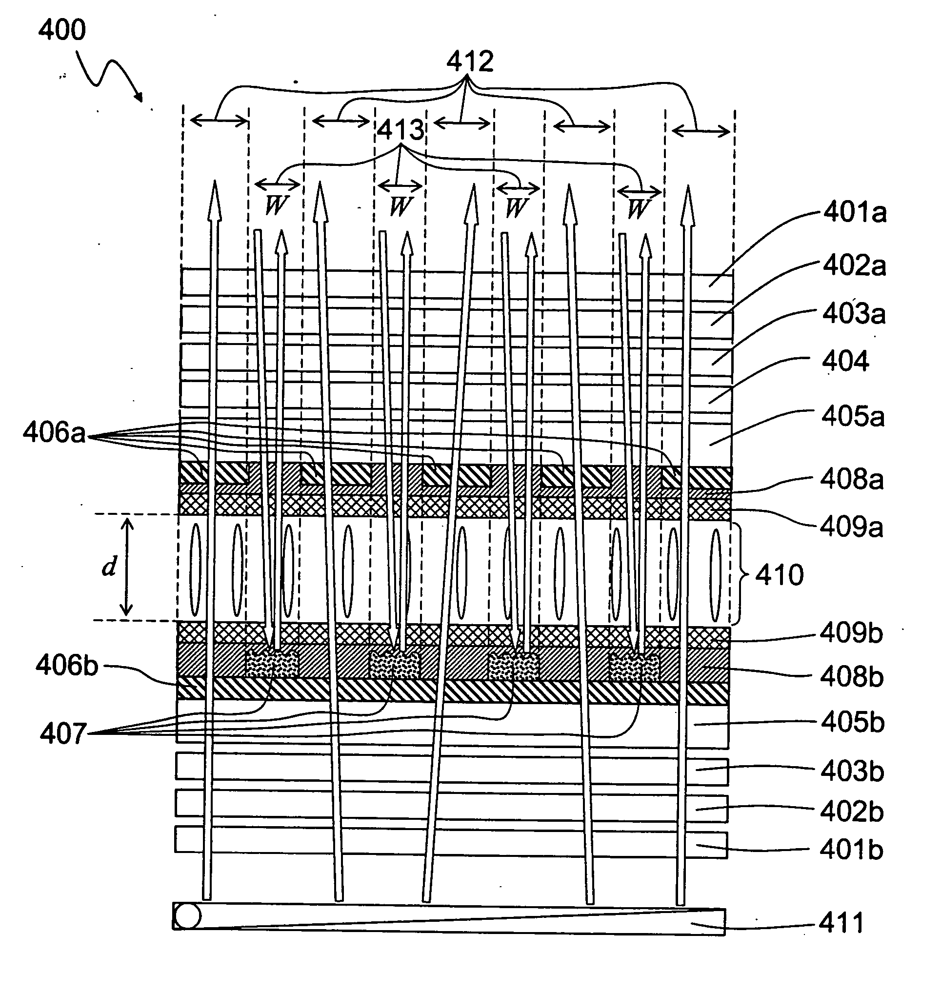
[0131]FIG. 4 shows the structure of a first embodiment of the transflective LCD 400 with uniform cell gap configuration of the present invention which consists of a first transparent substrate 405 a coated with a patterned ITO layer 406a, a first non-conductive planar layer 408a, and a first vertical alignment film 409a; a second transparent substrate 405b coated with a non-patterned ITO layer 406b, a patterned reflector 407, a second non-conductive planar layer 408b, and a second vertical alignment film 409b; and a vertically aligned negative dielectric anisotropic nematic liquid crystal layer 410 with thickness d sandwiched between the first vertical alignment film 409a and the second vertical alignment film 409b.

[0132] A negative birefringence c-film 404, a first quarter-wave retardation film 403a, a first half-wave retardation film 402a, and a first polarizer 401a are further laminated on the outer surface of the first substrate 405a, wherein the negative birefringence c-film 4...

second embodiment

[0140] In the first embodiment, the common electrode pattern on the first substrate is mutually complementary with the reflector pattern on the second substrate; therefore, the first substrate aligns with the second substrate. To avoid that alignment requirement, FIG. 10 shows the schematic structure according to the second embodiment of the transflective LCD 900 with uniform cell gap configuration according to the present invention. The structure in the second embodiment includes a first transparent substrate 905a coated with a non-patterned ITO layer 906a and a first vertical alignment film 909a, a second transparent substrate 905b coated with a patterned ITO layer 906b, a patterned reflector 907, a non-conductive planar layer 908, and a second vertical alignment film 909b, a vertically aligned negative dielectric anisotropic nematic liquid crystal layer 910 with thickness d sandwiched between the first vertical alignment film 909a and the second vertical alignment film 909b. A ne...


PUM

PropertyMeasurementUnit
pretilt anglesaaaaaaaaaa
incident angleaaaaaaaaaa
transparentaaaaaaaaaa

Abstract

A transflective liquid crystal display with uniform cell gap configuration throughout the transmissive and the reflective display region is invented. Mutually complementary common electrode pattern and reflector pattern or mutually complementary ITO pixel electrode pattern and reflector pattern produce an electric field in the transmissive display region that has a uniform longitudinal field and an electric field in the reflective display region that is a fringing field. An initially vertically aligned negative dielectric anisotropic nematic liquid crystal material between the electrodes forms a smaller tilt angle with respect to the substrate normal in the reflective display region while a larger tilt angle with respect to the substrate normal in the transmissive display region. Consequently, the ambient incident light experiences smaller phase retardation in the reflective display region while the light from the backlight source experiences larger phase retardation. Since the ambient light passes through the reflective display region twice while the light from the backlight source passes through the transmissive display region only once, by properly designing the electrodes and the reflector width, the light from both ambient light source and backlight source will experience almost the same phase retardation in both reflective and transmissive display regions. As a result, the electro-optical performance curves of both transmissive display mode and reflective display mode overlap.

Description

FIELD OF THE INVENTION [0001] This invention relates to transflective liquid crystal displays and, in particular, to designing the common electrode and the pixel electrode to generate a longitudinal electric field in the transmissive display region and to generate a fringing field in the reflective display region. Therefore, the initially vertically aligned negative dielectric anisotropic nematic liquid crystal molecules will form a smaller tilt angle with respect to the substrate normal in the reflective display region and form a larger tilt angle with respect to the substrate normal in the transmissive display region. Consequently, the ambient incident light experiences smaller phase retardation in the reflective display region while the light from the backlight source experiences larger phase retardation. Since the ambient light passes through the reflective display region twice while the light from the backlight source passes through the transmissive display region only once, by...

Claims


Application Information

Patent Timeline
Patent Type & Authority Applications(United States)
IPC IPC(8): G02F1/1335
CPCG02F1/133555G02F2001/134381G02F1/134381
Inventor ZHU, XINYUGE, ZHIBINGWU, SHIN-TSON
Owner INNOLUX CORP
Why Eureka
Try Eureka