Eureka AIR delivers breakthrough ideas for toughest innovation challenges, trusted by R&D personnel around the world.

Optical film, liquid crystal panel, and liquid crystal display apparatus

a liquid crystal display and optical film technology, applied in non-linear optics, instruments, optics, etc., can solve the problem that the conventional liquid crystal display apparatus hardly develops a colorless neutral display in all azimuth angle directions, and achieve the effect of reducing the thickness of the liquid crystal display apparatus

Active Publication Date: 2006-10-26
NITTO DENKO CORP
View PDF18 Cites 29 Cited by
  • Summary
  • Abstract
  • Description
  • Claims
  • Application Information

AI Technical Summary

Benefits of technology

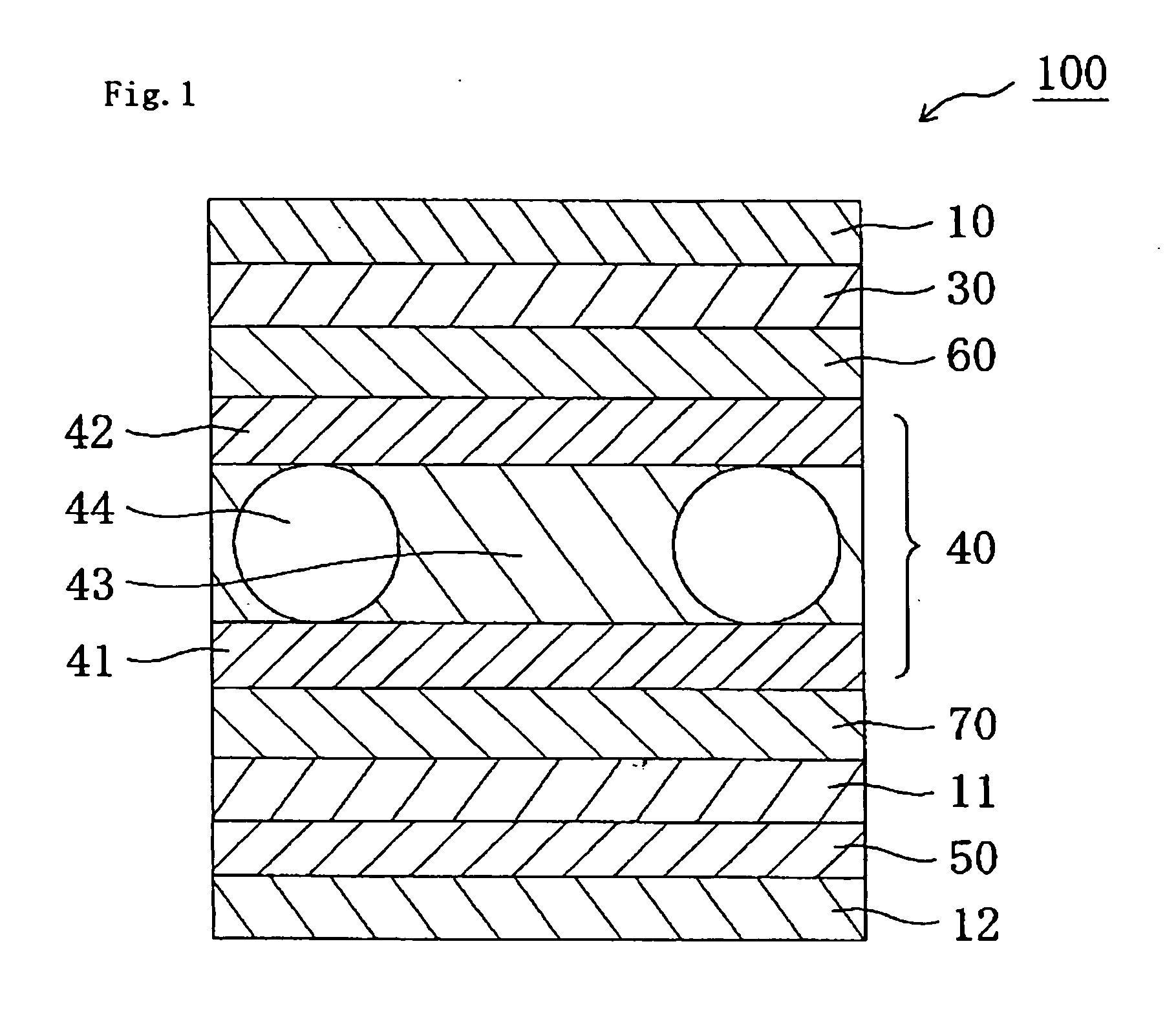
[0016] In a preferred embodiment, the optical film further includes an easily adhesive layer between the birefringent layer and one of a pressure-sensitive adhesive layer formed of the pressure-sensitive adhesive and an adhesive layer formed of the adhesive.
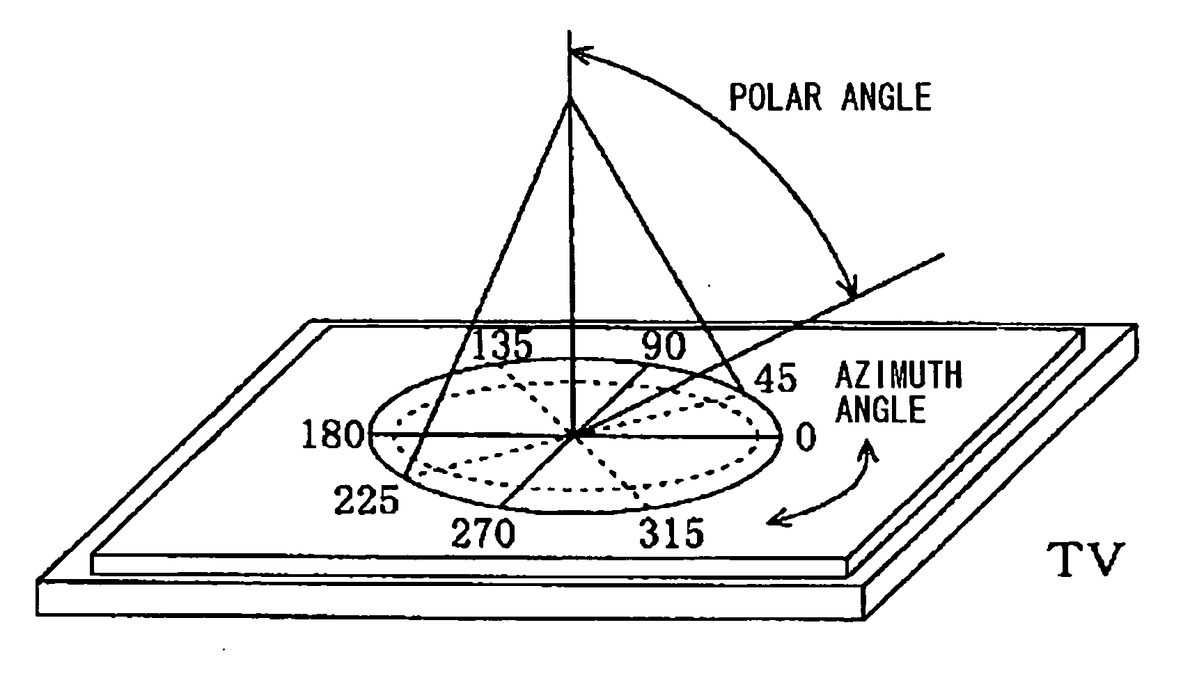
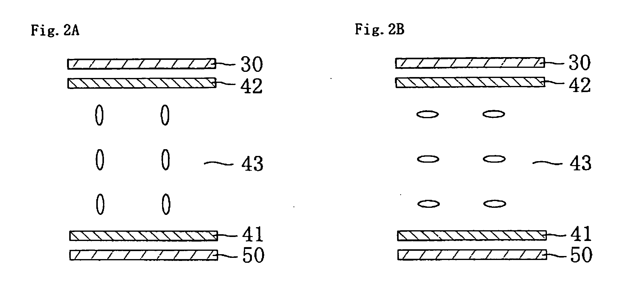
[0026] The present invention can provide: an optical film suitable for a liquid crystal display apparatus providing a colorless neutral display in all azimuth angle directions; a liquid crystal panel employing the optical film; and a liquid crystal display apparatus employing the liquid crystal panel. Such an effect can be provided significantly by laminating directly a polarizer, and a birefringent layer having a relationship of nx>ny=nz and positive uniaxial property through a pressure-sensitive adhesive or an adhesive and without a transparent protective film arranged therebetween. Therefore, reduction in thickness of the liquid crystal display apparatus may also be realized.

Problems solved by technology

However, the conventional liquid crystal display apparatus hardly develops a colorless neutral display in all azimuth angle directions.

Method used


Image

  • Optical film, liquid crystal panel, and liquid crystal display apparatus
  • Optical film, liquid crystal panel, and liquid crystal display apparatus
  • Optical film, liquid crystal panel, and liquid crystal display apparatus

Examples


reference example 1

Production of Polarizer

[0241] A polyvinyl alcohol film was colored in an aqueous solution containing iodine, and the resultant was uniaxially stretched to a six times length between rolls with different speed ratios in an aqueous solution containing boric acid, to thereby produce a polarizer.

reference example 2

Preparation of Polyvinyl Alcohol-Based Adhesive

[0242] An aqueous solution of a polyvinyl alcohol-based adhesive was prepared by adjusting to a concentration of 0.5wt % an aqueous solution containing 20 parts by weight of methylol melamine with respect to 100 parts by weight (degree of acetylation of 13%) of a polyvinyl alcohol resin subjected to acetoacetyl modification.

example 1

[0243] Production of First Birefringent Layer

[0244] A continuous norbornene-based resin film (“ZEONOR”, tradename, available from Zeon Corporation, thickness of 100 μm, photoelastic coefficient of 3.10×10⁻¹² m2 / N) was uniaxially stretched to a 1.46 times length at 150° C., to thereby produce a continuous first birefringent layer. The first birefringent layer had a thickness of 80 μm, an in-plane retardation Δnd of 140 nm, and a thickness direction retardation Rth of 140 nm.

(Production of Laminate of TAC / Polarizer / First Birefringent Layer)

[0245] Triacetyl cellulose (TAC) (thickness of 80 μm) and the polarizer were laminated by using an adhesive.

[0246] A surface of the thus-obtained first birefringent layer was subjected to easily adhesive treatment (silicon primer, “APZ6661”, trade name, available from Dow Corning Toray Co., Ltd., thickness of easily adhesive layer=50 nm), and the first birefringent layer was laminated on a polarizer side of the laminate of TAC and the polarizer...


PUM


Abstract

There is provided: an optical film suitable for a liquid crystal display apparatus providing a colorless neutral display in all azimuth angle directions; a liquid crystal panel employing the optical film; and a liquid crystal display apparatus employing the liquid crystal panel. An optical film includes a transparent protective film, a polarizer, and a birefringent layer having a relationship of nx>ny=nz and positive uniaxial property, in the stated order, in which the polarizer and the birefringent layer are laminated directly through one of a pressure-sensitive adhesive and an adhesive.

Description

BACKGROUND OF THE INVENTION [0001] 1. Field of the Invention [0002] The present invention relates to an optical film, a liquid crystal panel, and a liquid crystal display apparatus. The present invention more specifically relates to an optical film suitable for a liquid crystal display apparatus providing a colorless neutral display in all azimuth angle directions, to a liquid crystal panel employing the optical film, and to a liquid crystal display apparatus employing the liquid crystal panel. [0003] 2. Description of the Related Art [0004]FIG. 5A is a schematic sectional view of a typical conventional liquid crystal display apparatus, and FIG. 5B is a schematic sectional view of a liquid crystal cell to be used for the liquid crystal display apparatus. A liquid crystal display apparatus 900 is provided with: a liquid crystal cell 910; retardation plates 920 and 920′ arranged on both sides of the liquid crystal cell 910; and polarizing plates 930 and 930′ arranged on outer sides of...

Claims


Application Information

Patent Timeline
IPC IPC(8): G02F1/1335
CPCG02F1/133528G02F2202/28G02F1/133634G02F1/1335
Inventor MURAKAMI, NAOYOSHIMI, HIROYUKITAKEDA, KENTAROUKIYA, YOSHIYUKI
Owner NITTO DENKO CORP
Why Eureka
Eureka Blog
Learn More