Gas leakage monitoring method and its system

a monitoring method and gas leakage technology, applied in the field of gas leakage monitoring method and its system, can solve the problems of difficult to take an optimum action, difficult to locate the leakage point of hydrogen gas, device is susceptible to malfunction, etc., and achieves the effect of hardening the stoppage of the leakage gas

Inactive Publication Date: 2006-10-26
SHIKOKU RES INST
View PDF3 Cites 27 Cited by
  • Summary
  • Abstract
  • Description
  • Claims
  • Application Information

AI Technical Summary

Problems solved by technology

In particular, hydrogen gas is very difficult to locate the leakage point for the reasons that the hydrogen gas is tasteless, colorless, and odorless and the known city gas detector or the like cannot be used, as it is, to detect the hydrogen gas because of different properties of those gases.
However, when a flame is invisible to the naked eye under sunlight in the daytime (e.g., in the case of a hydrogen flame), it has been difficult to take an optimum action because of incapability in safely locating the ignition point even with such a device being operated.
This leads to a problem that the device is susceptible to malfunction and reliability is insufficient.
Further, because a region where hot air generated by a flame is ejected and reside, or actual temperatures around wall surfaces, pipes, etc., which are heated to high temperatures, cannot be sensed with the naked eye, a difficulty arises in confirming a high-temperature region around the flame, thus making it harder to stop the leakage gas and perform extinguishing activities.
When observing a flame by a thermo-camera for visualizing an infrared ray, radiation from high-temperature portions, such as wall surfaces and pipes heated by the flame, is so strong that it is difficult to locate the flame shape and the position where the flame is generated.

Method used


Image

  • Gas leakage monitoring method and its system
  • Gas leakage monitoring method and its system
  • Gas leakage monitoring method and its system

Examples


embodiment 1

[0089]FIG. 9 shows one example the configuration of a gas leakage monitoring system according to Embodiment 1.

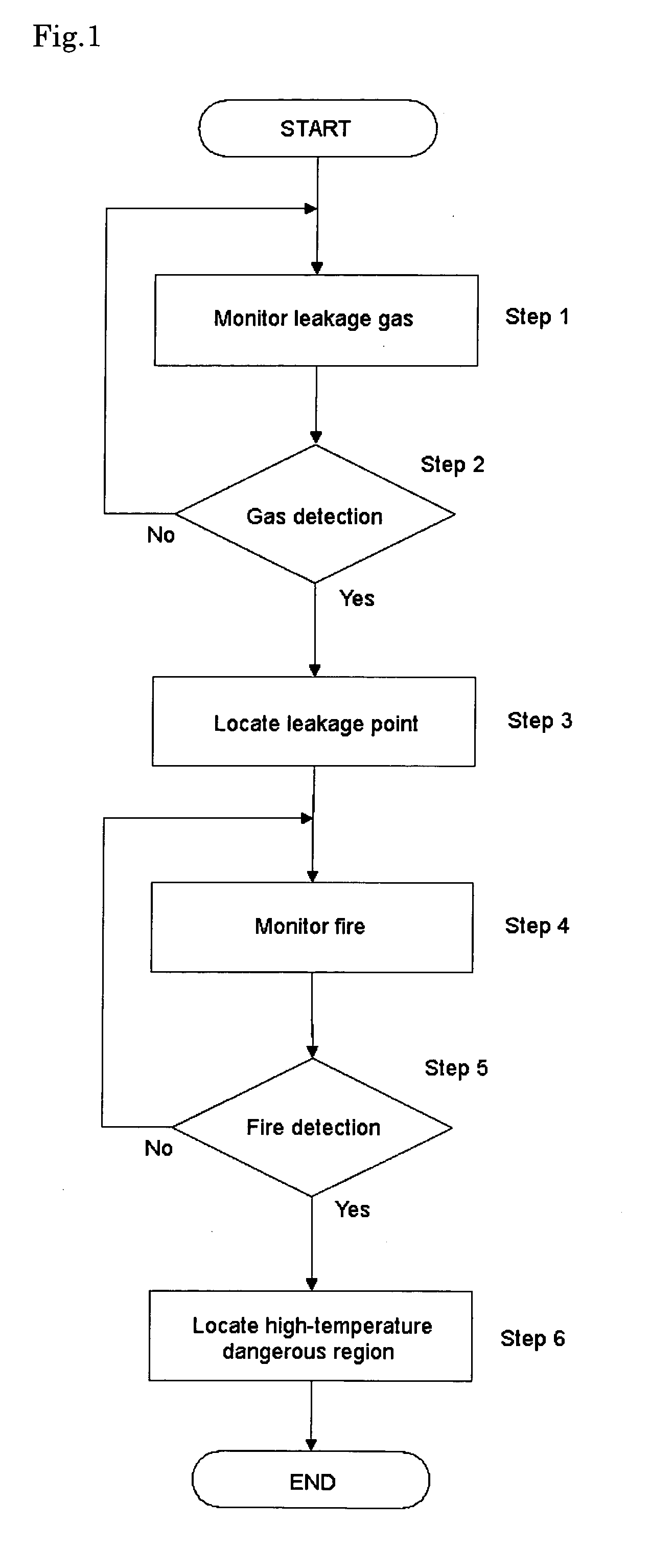
[0090] The system of Embodiment 1 is able to monitor leakage gas, locate a gas leakage point, monitor a flame, and to visualize a high-temperature dangerous region.

[0091] Referring to FIG. 9, numeral 10 denotes a personal computer including an image processing program. Connected to the personal computer 10 are a time synchronizing signal generator 203 and a Raman scattering light adapted camera 11a both serving as a leakage gas image pickup means, a visible light adapted camera 12 serving as a background image pickup means, an ultraviolet light adapted camera 11b serving as a flame image pickup means, and a thermo-camera 30 serving as an infrared image pickup means via cables.

[0092] Image pickup targets of the Raman scattering light adapted camera 11a and the ultraviolet light adapted camera 11b are set to the monitoring target. When an optical band-pass filter 3 is const...

embodiment 2

[0132]FIG. 13 is a schematic diagram showing an experimental system in which hydrogen is used as the target gas.

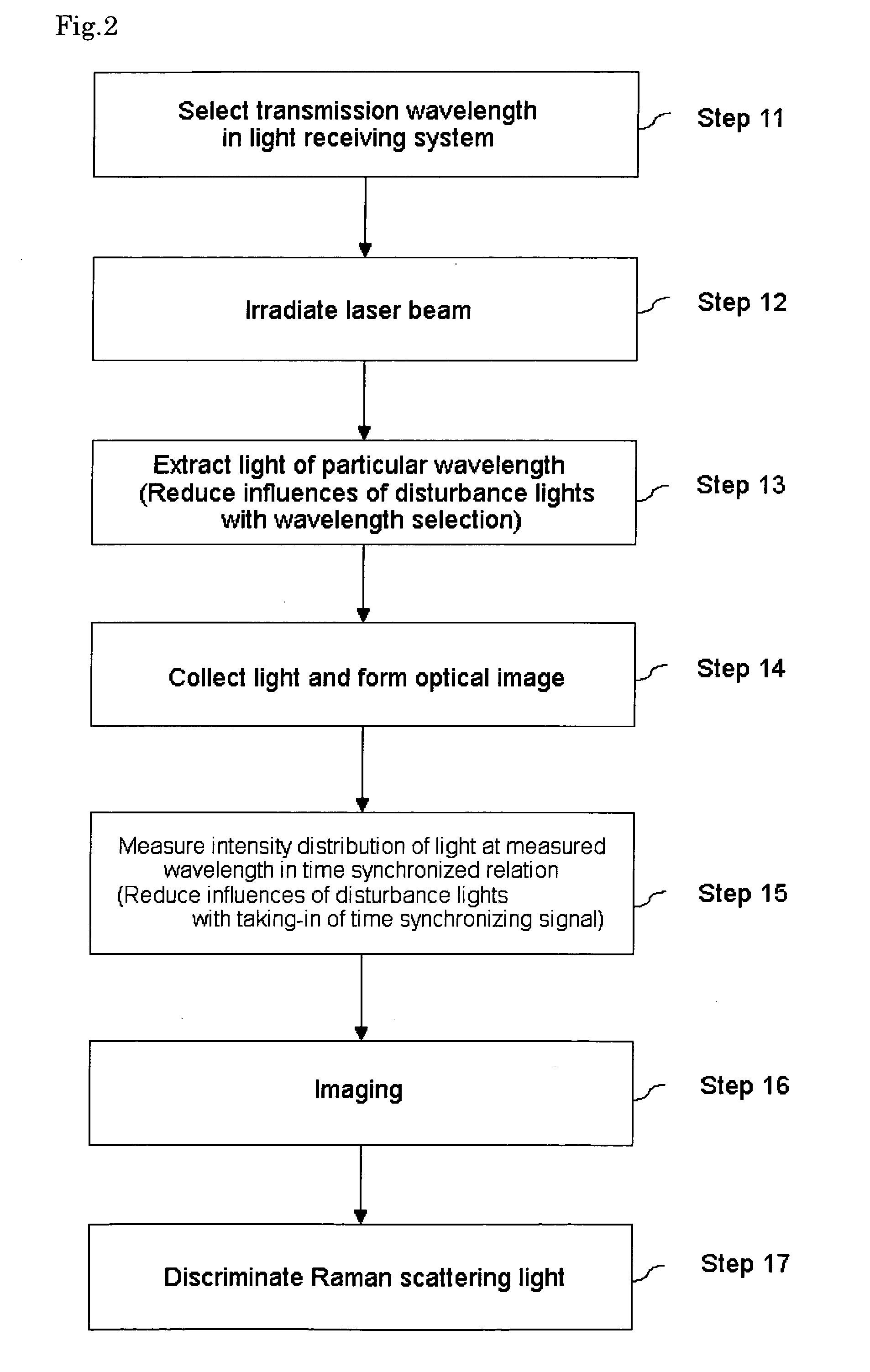
[0133] An experiment was conducted by employing the system configuration shown in FIG. 13, hydrogen gas as the target gas, and a 266-nm fourth harmonic of a YAG laser as the laser beam source. As a result, as shown in FIG. 14, the Raman scattering spectrum emitted from the hydrogen gas has an emission region about a wavelength 299.1 nm being as the center. Correspondingly, the optical band-pass filter 3 has the transmission wavelength center for a light having a wavelength of 299.1 nm and its transmission wavelength range has a half width at half maximum of 1 nm. Thus, the optical band-pass filter allows an ultraviolet light having a wavelength range of 299.1 nm±1 nm to pass through the filter, and cuts off lights of other wavelengths. When strong fluorescence is generated in an environment for measuring the Raman scattering light, the measurement can also be made using t...

embodiment 3

[0135]FIG. 16 is a schematic diagram showing the configuration of an experimental system for verifying visualization of leakage gas.

[0136] As a result of conducting an experiment for verifying visualization of leakage gas by employing the system configuration shown in FIG. 16, hydrogen gas as the target gas, and a 266-nm fourth harmonic of a YAG laser as the laser beam source, an image of the Raman scattering light was obtained as shown in FIG. 17.

[0137] The optical band-pass filter has a central wavelength of 299.1 nm, and its transmission wavelength range has a half width at half maximum of 1 nm.

[0138]FIG. 17 shows the colored images at various values of the hydrogen concentration. As shown in FIG. 17, the colored image becomes clearer by degrees as the hydrogen concentration increases.

[0139]FIG. 18 shows a visualized image of a hydrogen flame, which is obtained by coloring the image measured using the above-described system.

[0140] The optical band-pass filter has a central w...


PUM

PropertyMeasurementUnit
transmission wavelengthaaaaaaaaaa
wavelengthaaaaaaaaaa

Abstract

A gas leakage monitoring method and system capable of ensuring safety of a gas utilization facility by visualizing invisible-to-naked-eye leakage gas and / or flame of leakage gas into the form of an image. The gas leakage monitoring method comprises the steps of collecting a detected light of a particular wavelength, which is caused by leakage gas and / or a flame of the leakage gas, in a space to be monitored, converting the detected light into an electronic image, amplifying and then converting the electronic image into an optical image again, and imaging the spatial intensity distribution of the particular wavelength light. The gas leakage monitoring system comprises first means for collecting a detected light of a particular wavelength, which is caused by leakage gas and / or a flame of the leakage gas, in a space to be monitored, second means for converting the detected light into an electronic image, and amplifying and then converting the electronic image into an optical image again, and third means for imaging the spatial intensity distribution of the particular wavelength light.

Description

TECHNICAL FIELD [0001] The present invention relates to a technique for visualizing invisible-to-naked-eye gas and / or flame into the form of an image, thereby, for example, remotely determining the presence or absence of a gas leakage and / or a flame, a leakage point, and a high-temperature dangerous region with high safety. More particularly, the present invention relates to a gas leakage monitoring method and system, which are adapted for continuous monitoring and are suitably used for, e.g., the operation of a hydrogen gas utilization facility, such as hydrogen supply stations and fuel cells, and monitoring of a hydrogen gas leakage. BACKGROUND ART [0002] Hitherto, leakage gas has been detected by bringing sucked gas into direct contact with a sensor portion and measuring gas concentration based on a change in value of electrical resistance or current. However, such a known gas detector is of the sensor type that an area capable of being monitored by one detector is narrow and lea...

Claims


Application Information

Patent Timeline
Patent Type & Authority Applications(United States)
IPC IPC(8): G01C3/08G06K9/00F23N5/24G01M3/38G01N21/33
CPCF23N5/24G01J3/36G01J3/44G01J5/0018G01N21/65G01J2005/0077G01M3/38G01N21/33G01J5/602
Inventor NINOMIYA, HIDEKIICHIKAWA, KOJIKAWAHARA, KENMIKI, HIROFUMIMORIYA, TASUKU
Owner SHIKOKU RES INST
Why Eureka
Try Eureka