Apparatus and method for modified horizontal directional drilling assembly

a technology of horizontal directional drilling and assembly, which is applied in the direction of directional drilling, manufacturing tools, and well accessories, etc., can solve the problems of limited horizontal distances and bore hole diameters that may be achieved using super singles, limited horizontal distances produced by conventional devices and methods, and increased drilling capacity. , the effect of increasing the diameter and the capacity of drilling pipe rotation

Inactive Publication Date: 2006-11-02
ASTEC INDS
View PDF3 Cites 31 Cited by
  • Summary
  • Abstract
  • Description
  • Claims
  • Application Information

AI Technical Summary

Benefits of technology

[0008] Among the advantages of the invention is to provide a drilling assembly that produces an increased capacity for drill pipe rotational, thrust and pull-back forces. It is also an advantage of the invention to provide a drilling assembly that is capable of producing longer well bores and well bores having a greater diameter than those produced by conventional drilling assemblies. It another advantage of the invention to provide a drilling assembly that is capable of entering the earth and drilling a well bore at an angle steeper than conventional horizontal directional drill assemblies. It is still another advantage of the invention to provide a drilling assembly that is capable of entering the earth and drilling a well bore at an angle closer to horizontal than conventional vertical drill assemblies. It is yet another advantage of the invention to provide a drilling assembly that eliminates the need for heavy drill pipe or drill collars to exert downward force on the drill bit. It is a further advantage of the invention to provide a drilling assembly that is more easily transported. It is a still further advantage of the invention to provide a drilling assembly that may be anchored to the ground so as to increase performance specifications. It is also an advantage of the invention to provide a drilling assembly that eliminates the need for cables, winches, hydraulic cylinders, chain systems and the like to provide rotational, thrust and pull-back forces. It is also an advantage of the invention to provide a drilling assembly that reduces the damage and wear to the threaded end of a drill string section when the top drive or rotary table engages the threaded end of the drill string section. It another advantage of the invention to provide a drilling assembly that reduces the amount of time required to perform make-up and break-out operations on the drill pipe and / or casing tool joints. It is a further advantage of the invention to provide a drilling assembly that includes pipe handling arms adapted to be pinned to the sub-structure for easy removal during transport. It is a still further advantage of the invention to provide a drilling assembly that is adapted to perform vertical and horizontal drilling applications with a tube-in-tube drill pipe or a tube-in-tube drill pipe string. It is another advantage of the invention to provide a drilling assembly that may be continuously operated in the event of a power unit failure.
[0009] Additional advantages of this invention will become apparent from an examination of the drawings and the ensuing description.
[0010] As used herein, the term “drilling a drill pipe into a drilling surface” includes drilling a bore hole into which a drill pipe or a drill pipe string is pulled. The term “drilling a drill pipe into a drilling surface” also includes pulling the drill pipe or the drill pipe string out of the bore hole.
[0011] As used herein, the term “drilling surface” includes the Earth's subsurface strata and any other medium into which a bore hole may be drilled.
[0012] As used herein, the term “hydraulic actuator” includes hydraulic cylinders, hydraulic rotary actuators, pneumatic cylinders and any other device or system in which pressurized fluid is used to impart a mechanical force.
[0013] As used herein, the term “tube-in-tube” refers to a type of drill pipe or drill pipe string characterized by an outer drill pipe wall and a substantially axially positioned inner drill pipe wall that is substantially surrounded by the outer drill pipe wall.

Problems solved by technology

However, the distances of the horizontal runs produced by conventional devices and methods are limited by the capability of the top drive to apply thrust and pull-back forces to the drill pipe.
The diameters of the horizontal runs are also limited by the ability to apply thrust and pull-back forces to the drill pipe.
Thus, the horizontal distances and bore hole diameter that may be achieved using a super single are limited.
Still further, conventional drilling rigs include power units that are separate from the drilling apparatus and therefore require multiple truckloads to transport the drill rig.
As a result, convention drilling machines are very heavy and require multiple truckloads to transport.
Weighted drill collars, however, are not effective in the horizontal direction.
Further, conventional oil, gas and methane machines frequently damage the threaded end of a drill string section when the top drive or rotary table engages the threaded end of the drill string section.
Still further, conventional drilling assemblies do not include a roller drill pipe guide bushing assembly adapted to reduce the wear and damage to the drill pipe string.

Method used


Image

  • Apparatus and method for modified horizontal directional drilling assembly
  • Apparatus and method for modified horizontal directional drilling assembly
  • Apparatus and method for modified horizontal directional drilling assembly

Examples


Embodiment Construction

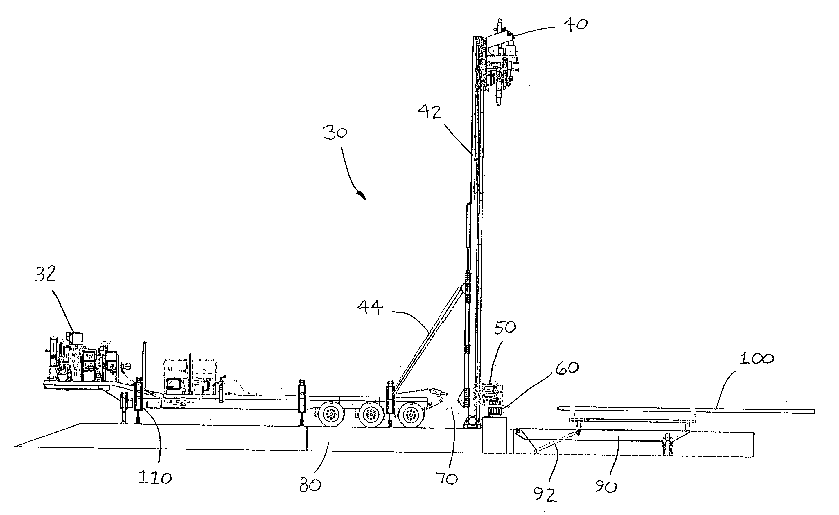
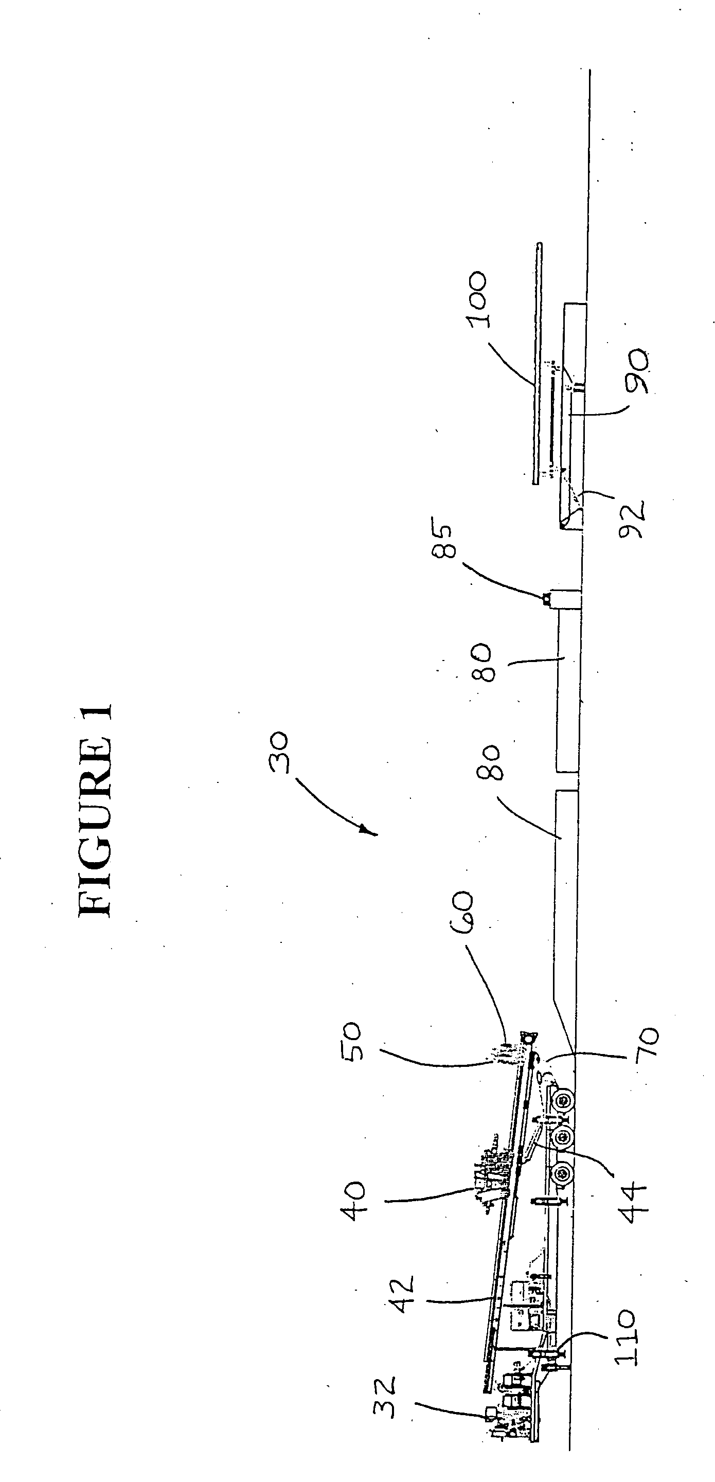
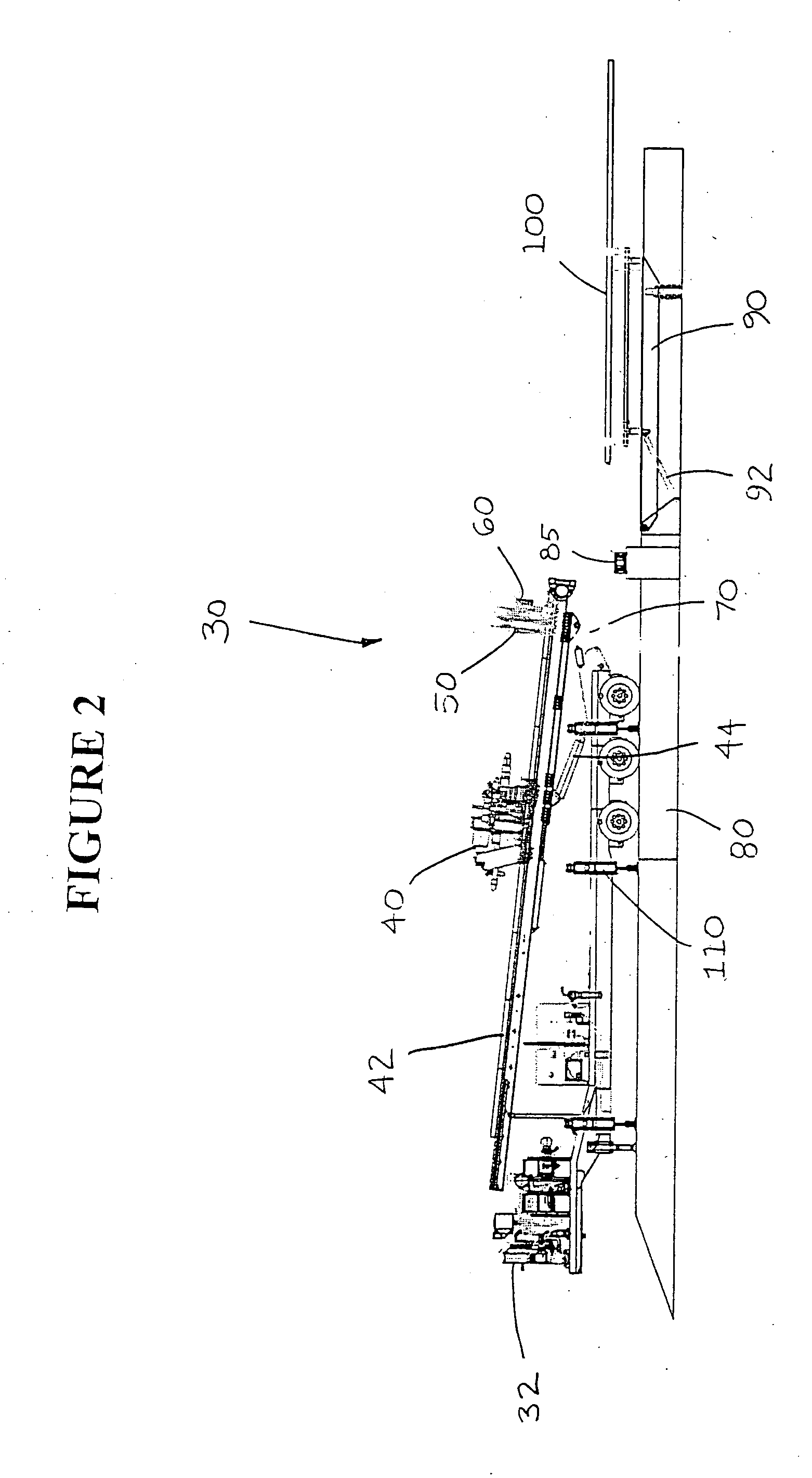
[0034] Referring now to the drawings, the preferred embodiment of the apparatus and method for the modified horizontal directional drilling assembly of the invention is illustrated in FIGS. 1 through 12. More particularly, as shown in FIGS. 1 through 12, the preferred modified horizontal directional drilling assembly (“modified HDD assembly”) is designated generally by reference numeral 30. The preferred modified HDD assembly 30 is adapted for use in both horizontal directional drilling applications and vertical subsurface drilling applications such as oil, gas and methane subsurface drilling.

[0035] As shown in FIG. 1, the preferred modified HDD assembly 30 preferably includes a pair of power units 32 and 34 (not shown). The preferred power units are diesel engines, but it is contemplated within the scope of the invention that any suitable power source such as electric motors, diesel engines and generators and the like may be used. A plurality of power units are provided so that dr...


PUM


Abstract

An apparatus and method for a modified horizontal directional drilling assembly for drilling pipe into a drilling surface. The drilling assembly comprises a power unit for supplying power to the assembly, a thrust frame adapted to be moved between a position substantially parallel to the drilling surface and a position substantially perpendicular to the drilling surface and a means for moving the thrust frame. The drilling assembly further comprises a rotary and carriage assembly mounted on the thrust frame. The rotary and carriage assembly is adapted to apply rotational, thrust and pull-back forces to the drill pipe. The drilling assembly is adapted to drill pipe into the drilling surface at any angle relative to the drilling surface between substantially parallel to the drilling surface and substantially perpendicular to the drilling surface. The method includes the steps of placing a drill pipe onto the drilling assembly, moving the thrust frame to a desired drilling angle, moving the rotary and carriage assembly into direct contact with the drill pipe, applying rotational, thrust and pull-back forces to the drill pipe, and drilling the pipe into the drilling surface.

Description

FIELD OF THE INVENTION [0001] This invention relates generally to assemblies and methods for subsurface drilling, and particularly to assemblies and methods for horizontal directional and vertical subsurface drilling. BACKGROUND AND DESCRIPTION OF THE PRIOR ART [0002] It is known to use a vertical drilling rig in oil, gas and coal bed methane well drilling. Conventional vertical drilling rigs use heavy drill pipe or drill collars in order to exert downward force on the drill bit as it enters the earth's surface and begins the well bore. As the drill bit of the conventional vertical drilling rig drills deeper below the earth's surface, it is sometimes necessary to apply force in the opposite direction of the drilling direction (pull-back force) in order to prevent placing too much weight on the drill bit and causing damage to or failure of the drill bit. [0003] It is also known to drill oil, gas and methane wells in a vertical direction initially and then deviate or turn the well bor...

Claims


Application Information

Patent Timeline
Patent Type & Authority Applications(United States)
IPC IPC(8): E21B19/08E21B21/00
CPCE21B15/04E21B7/04
Inventor RIEL, WILLIAM G.
Owner ASTEC INDS
Why Eureka
Try Eureka