Unlock instant, AI-driven research and patent intelligence for your innovation.

Digitally controlled threshold adjustment circuit

a threshold adjustment and digital control technology, applied in the field of electronic circuits, can solve the problems of bandwidth limitation, significant capacitive loading of the output of the dacs, bandwidth limitation,

Inactive Publication Date: 2006-11-02
AVAGO TECH INT SALES PTE LTD
View PDF3 Cites 2 Cited by
  • Summary
  • Abstract
  • Description
  • Claims
  • Application Information

AI Technical Summary

Benefits of technology

[0008] In one embodiment, the present invention is a threshold adjustment circuit including: a current digital-to-analog converter (DAC) for supplying or sinking a varying current; a differential pair of thin oxide transistors coupled to the DAC and coupled together at a common source node; a supply voltage having a voltage level above reliability of the pair of thin oxide transistors; and a third transistor for maintaining voltage of the common source node above a predetermined level and to disable the threshold adjustment circuit, wherein the bulk and source of each of the differential pair thin oxide transistors is coupled to the common source node and each of the differential pair thin oxide transistors is switched by a signal having an ON voltage level so that one of the thin oxide transistors is in saturation region and having an OFF voltage level so that the other thin oxide transistor is OFF but within its reliability limit.
[0009] In one embodiment, the present invention is a circuit for threshold adjustment of an input signal having a first and a second component. The threshold adjustment circuit includes: a first differential pair of first and second thin oxide transistors for decreasing a DC voltage component of the first or second component of the input signal; a second differential pair of third and fourth thin oxide transistors for increasing a DC voltage component of the first or the second component of the input signal; a power supply for providing a supply voltage having a voltage level above reliability of the thin oxide transistors, wherein each of the differential pair thin oxide transistors is switched by a signal that keeps each of the first, second, third, and fourth thin oxide transistors in saturation region.
[0010] In one embodiment, the present invention is a threshold adjustment circuit for a differential input signal. The threshold adjustment circuit includes: means for decreasing DC voltage component of either side of the differential input signal; means for increasing the DC voltage component of either side of the differential input signal; and means for generating a signal for switching between means for decreasing the DC voltage component and means for increasing the DC voltage component voltage of the input signal.

Problems solved by technology

However, in this configuration, the DACs' outputs have significant capacitive loading due to large DAC transistors needed to generate the required maximum current for the threshold adjustment.
In this case, the DACs heavily load Outp and Outn and thus causing bandwidth limitation.
Moreover, two current DACs occupy large silicon area.
This scheme also suffers from bandwidth limitation due to heavy capacitive loading of Outp and Outn.
In a case where low voltage transistors are being used with a supply voltage (VDD) above the reliability voltage limit, Sp and Sn switches may exhibit reliability problems due to over the limit terminal voltages.
All of above conventional implementations introduce bandwidth limitations on the signal path.
These circuits also occupy large silicon area.

Method used


Image

  • Digitally controlled threshold adjustment circuit
  • Digitally controlled threshold adjustment circuit
  • Digitally controlled threshold adjustment circuit

Examples


Embodiment Construction

[0020] In one embodiment, the present invention is a digitally controlled threshold adjustment circuit which does not impose any significant bandwidth reduction due to loading of the signal path. Since the circuit is digitally controlled, it can easily be incorporated into an adaptive algorithm that can automatically find the optimal point for sampling, without user intervention.

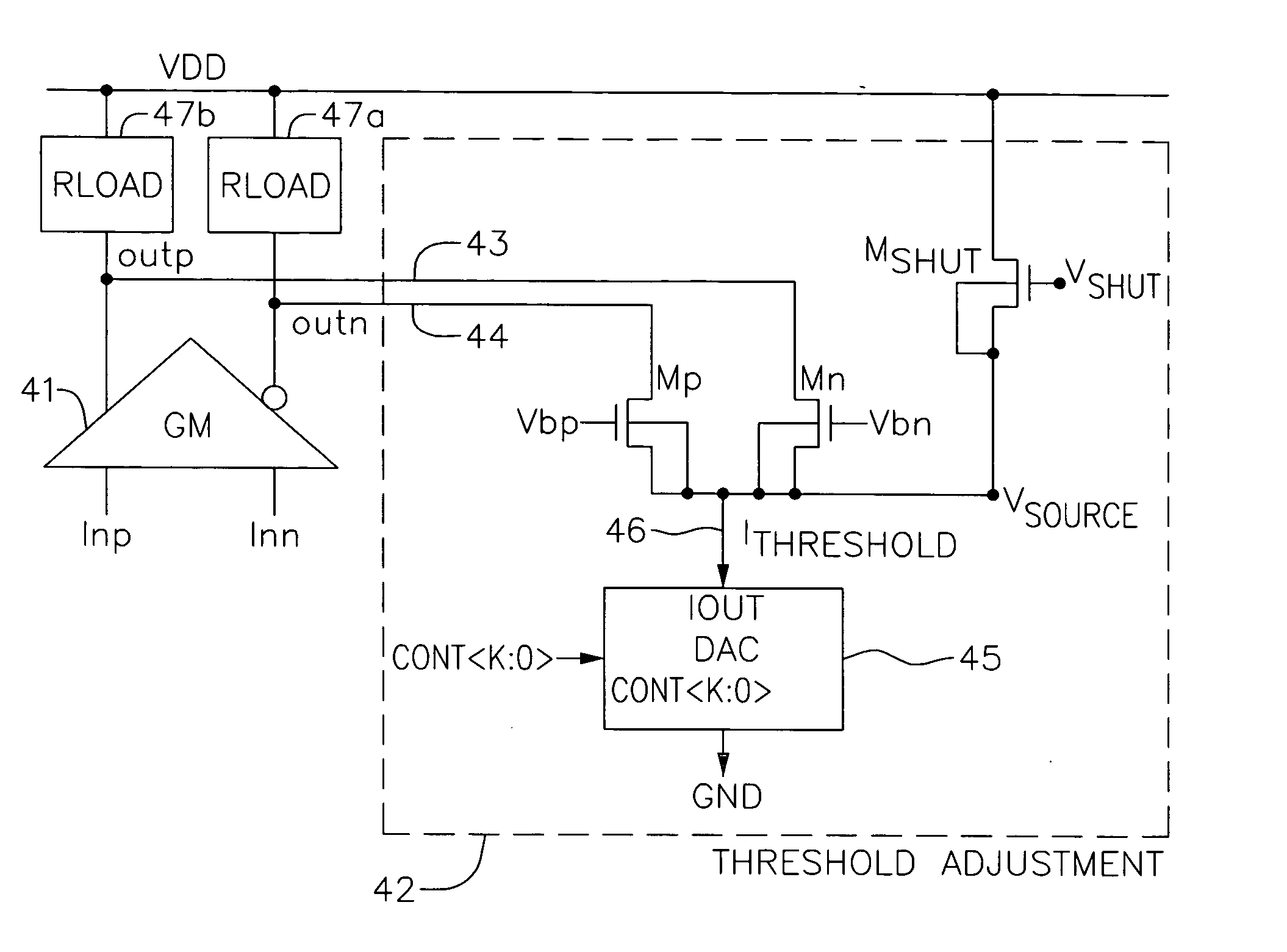
[0021]FIG. 4 is an exemplary circuit diagram of a threshold adjuster, according to one embodiment of the present invention. As depicted in FIG. 4, a threshold adjustment circuit 42 is connected to current summing nodes 43 and 44, which generate Outp and Outn, respectively. As an example, threshold adjustment circuit 42 can be connected to Outp and Outn at the output of a gain stage which includes a trans-conductance (GM) 41 sinking current from load impedances (RLOAD) 47a and 47b. Threshold adjustment circuit 42 includes a current DAC 45, which generates a threshold current 46 (Ithreshold). In one embodimen...


PUM


Abstract

A threshold adjustment circuit including: a current DAC for supplying or sinking a varying current; a differential pair of thin oxide transistors coupled to the DAC and coupled together at a common source node; a power supply for providing a supply voltage having a voltage level above reliability of the thin oxide transistors; and a third transistor for maintaining voltage of the common source node above a predetermined level and to disable the threshold adjustment circuit. The bulk and source of each of the differential pair thin oxide transistors is coupled to the common source node and each of the differential pair thin oxide transistors is switched by a signal to keep each of the differential pair thin oxide transistors in saturation region.

Description

FIELD OF THE INVENTION [0001] This application is related to electronic circuits, and more particularly to a digitally controlled threshold adjustment circuit. BACKGROUND OF THE INVENTION [0002] In optical communications, the transmitted signal over a fiber optic link will exhibit an asymmetric eye opening. For example, as depicted in FIG. 1A, a transmitted signal exhibits an asymmetric eye relative to vertical threshold of its sampler. As known to one skilled in the art, LOGIC 0 has significantly less vertical margin compared to LOGIC 1 due to the shown asymmetry. One way to alleviate the problem is to adjust the Direct Current (DC) component voltage levels of the single-ended signals Outp and Outn in order to level out the vertical margins of Outp and Outn with respect to the sampler. In the example of FIG. 1A, one can decrease the DC component voltage level of Outp, or increase the DC component voltage level of Outn to substantially reduce the asymmetric eye opening. This adjustm...

Claims


Application Information

Patent Timeline
Patent Type & Authority Applications(United States)
IPC IPC(8): H03L5/00
CPCH03K5/003H03K5/151H03K5/086
Inventor KOCAMAN, NAMIK KEMALMOMTAZ, AFSHIN
Owner AVAGO TECH INT SALES PTE LTD
Features
  • R&D
  • Intellectual Property
  • Life Sciences
  • Materials
  • Tech Scout
  • Unparalleled Data Quality
  • Higher Quality Content
  • 60% Fewer Hallucinations
Learn More