
Apparatus and method for reducing noise in an image

a technology of image noise reduction and apparatus, applied in the field of compression, can solve the problems of difficult adjustment of filtering to remove, and achieve the effects of reducing noise, reducing noise, and reducing nois

Inactive Publication Date: 2006-11-02
GVBB HLDG R L
View PDF20 Cites 6 Cited by
  • Summary
  • Abstract
  • Description
  • Claims
  • Application Information

AI Technical Summary

Benefits of technology

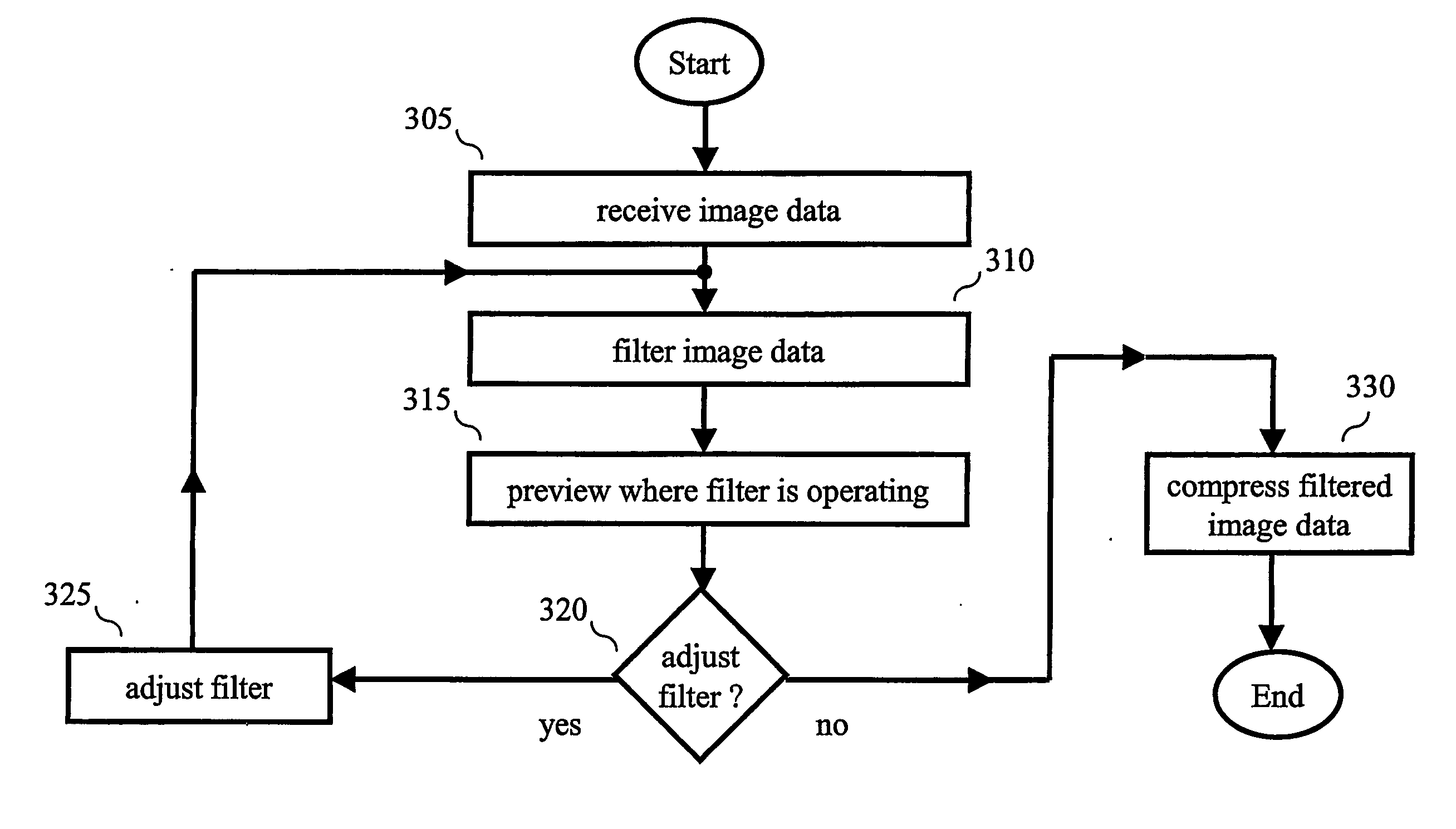
[0005] As noted above, when filtering image data, it may be difficult to adjust the filtering to remove, e.g., low-level noise from the image data, by viewing the filtered image. However, and in accordance with the principles of the invention, I have realized that displaying where the filtering is being performed on the image data to remove noise instead of, or in addition to, displaying the filtered image data improves the ability to quickly set filter parameters to increase the removal of even low-level noise from the image data.
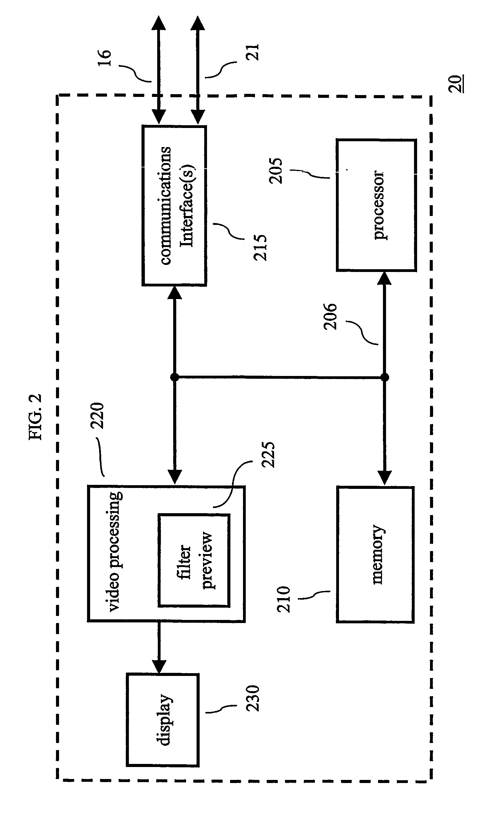
[0006] In an embodiment of the invention, an image processor includes Lee's local statistics filter (or Lee filter) for processing image data to remove noise therefrom. The Lee filter includes a smoothing control signal. During filtering of the image data, the smoothing control signal is converted to a monochrome video signal that is provided to a display instead of, or in addition to, the filtered image data. The displayed image representation of the smoothing control signal highlights edge activity in the filtered image. This display of edge activity makes it easier to locate noisy areas in the image data and fine-tune the amount of filtering to further reduce noise present in the image data and yet leave the desired image details alone. In particular, the display of the smoothing control signal of the Lee filter indicates light and dark areas. The dark areas indicate where the Lee filter is performing larger amounts of filtering on the image data while the brighter areas indicate where the Lee filter is performing smaller amounts of filtering on the image data.

Problems solved by technology

As noted above, when filtering image data, it may be difficult to adjust the filtering to remove, e.g., low-level noise from the image data, by viewing the filtered image.

Method used


Image

  • Apparatus and method for reducing noise in an image
  • Apparatus and method for reducing noise in an image
  • Apparatus and method for reducing noise in an image

Examples


Embodiment Construction

[0016] Other than the inventive concept, the elements shown in the figures are well known and will not be described in detail. Also, familiarity with image processing and content delivery is assumed and is not described in detail herein. For example, other than the inventive concept, microprocessors, memory, analog and digital image formats, content streaming, media players, compression, etc., are well known and not described in detail herein. In addition, the inventive concept may be implemented using conventional programming techniques, which, as such, will not be described herein. Finally, like-numbers on the figures represent similar elements. It should also be noted that the term “signal” includes both hardware forms (e.g., electrical) and software forms (e.g., a variable). In addition, it should be noted that the use of the term “memory” below encompasses machine readable storage mediums such as, but not limited to, hard disk drives, floppy diskettes, CD-ROMS (including writab...


PUM


Abstract

An image processor includes a Lee filter for processing image data to improve noise therefrom. The Lee filter includes a smoothing control signal. During filtering of the image data, the smoothing control signal is converted to a monochrome video signal that is provided to a display instead of, or in addition to, the filtered image data. The image projected by the display of the smoothing control signal highlights edge activity in the filtered image. This display of edge activity makes it easier to locate noisy areas in the image data and fine-tune the amount of filtering to further reduce noise present in the image data and yet leave the desired image details alone.

Description

BACKGROUND OF THE INVENTION [0001] The present invention generally relates to compression, and, more particularly, to preprocessing image data before compression to reduce the presence of noise in an image, whether a still image or a sequence of images such as in a video. [0002] Image data is typically large in size. This is especially so if the image data represents video. As such, and as known in the art, it is preferable to compress the image data before transmission, or even storage, of the image data. In this regard, there are numerous techniques for compressing image data that to one degree or another provide some level of fidelity to the original image data. [0003] However, when compressing image data, the image data may include noise that can adversely affect the compression efficiency since compression algorithms generally cannot distinguish noise from desired detail in the image. In other words, the size of the compressed image data may be larger than is necessary due to t...

Claims


Application Information

Patent Timeline
Patent Type & Authority Applications(United States)
IPC IPC(8): G06K9/40G06T5/00H04N7/26H04N7/30
CPCG06T5/002G06T2200/24G06T2207/10016H04N19/85H04N19/117H04N19/14H04N19/182H04N19/60G06T5/70
Inventor BEAZLEY, TODD MARTIN
Owner GVBB HLDG R L
Learn More