
Apparatus for forming a sequence of load carriers by means of a temporary store, and method for temporary storage

a technology of temporary storage and apparatus, applied in the direction of storage devices, loading/unloading, transportation and packaging, etc., can solve the problems of high investment cost, limited throughput capacity, and frequent insufficient single load carriers, and achieve high throughput capacity, low investment cost, and high storage capacity

Inactive Publication Date: 2006-11-02
SIEMENS AG
View PDF23 Cites 20 Cited by
  • Summary
  • Abstract
  • Description
  • Claims
  • Application Information

AI Technical Summary

Benefits of technology

[0007] The present invention provides a temporary store which is distinguished both by a high storage capacity and also by a high throughput capacity with a comparatively low investment outlay. In addition, a method is provided for the temporary storage of load carriers, the implementation of which is cost-effective and highly efficient.
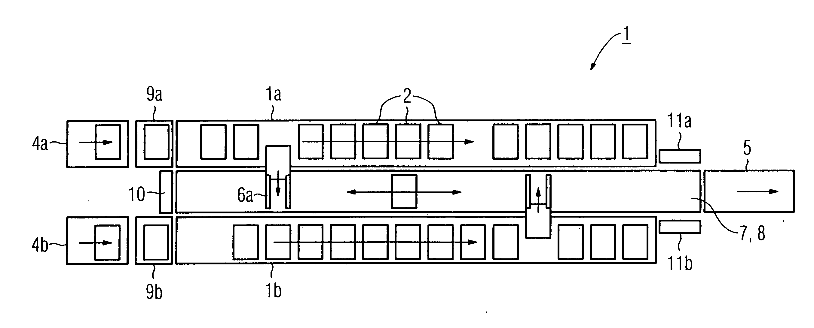
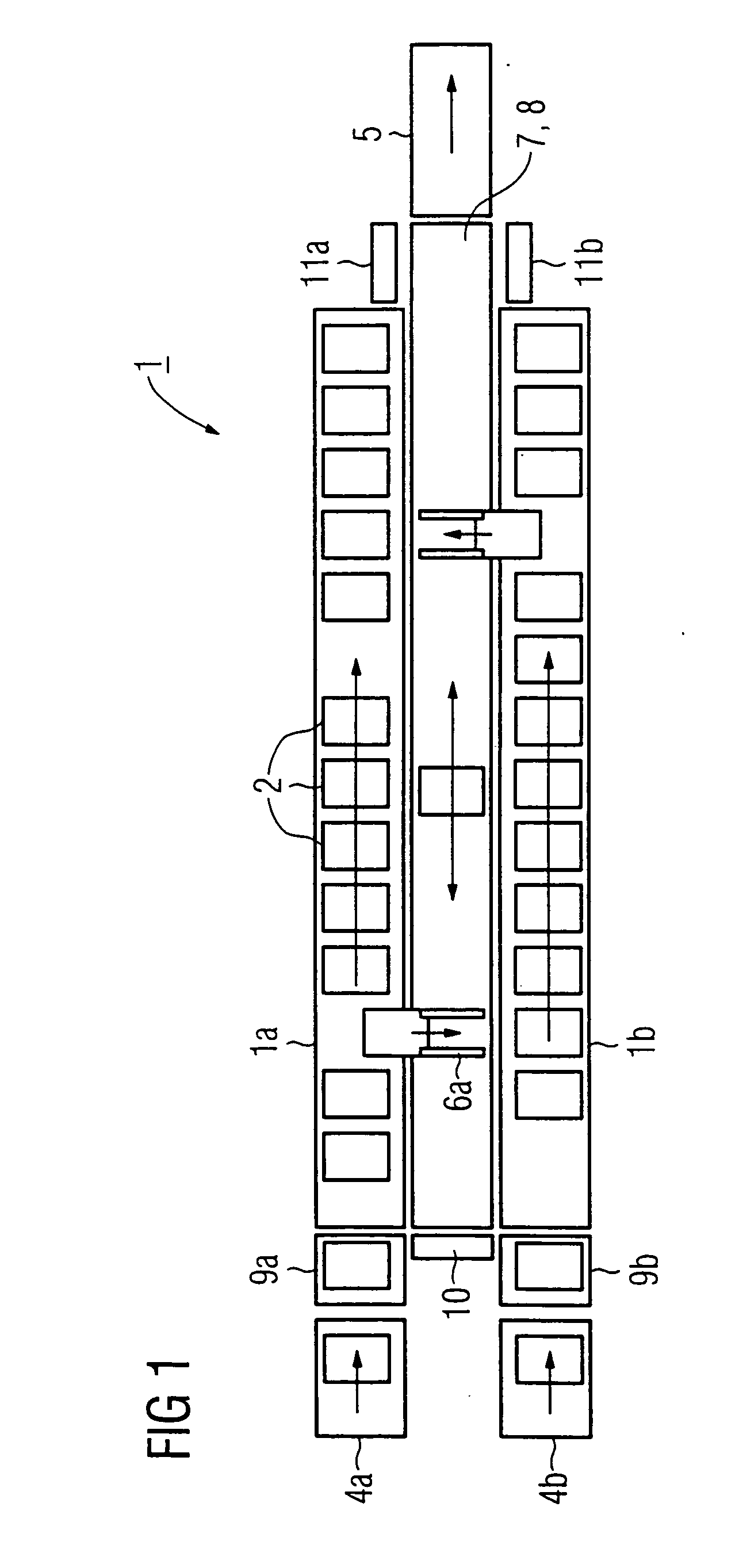
[0011] The feed-in device for feeding in load carriers newly to be temporarily stored may be fitted on an end side of the rack. As a result, a loss of storage places which would arise if the feed-in device were arranged on the longitudinal side of the rack is avoided. The feed-in device may be in the form of two separate conveying units, each conveying unit being assigned in each case to a unit of the rack. Since the feed-in device, which can be designed, for example, in the form of a customary band, belt, roller or chain conveyor, ends in a certain plane on the end side of the rack, a lifting device may be provided, for example, in the form of a conveying lift, on the end side of the rack which connects the feed-in device to the individual levels of the rack. Of course, in the case of a rack comprising two units, each unit may be provided with a lifting device of this type.
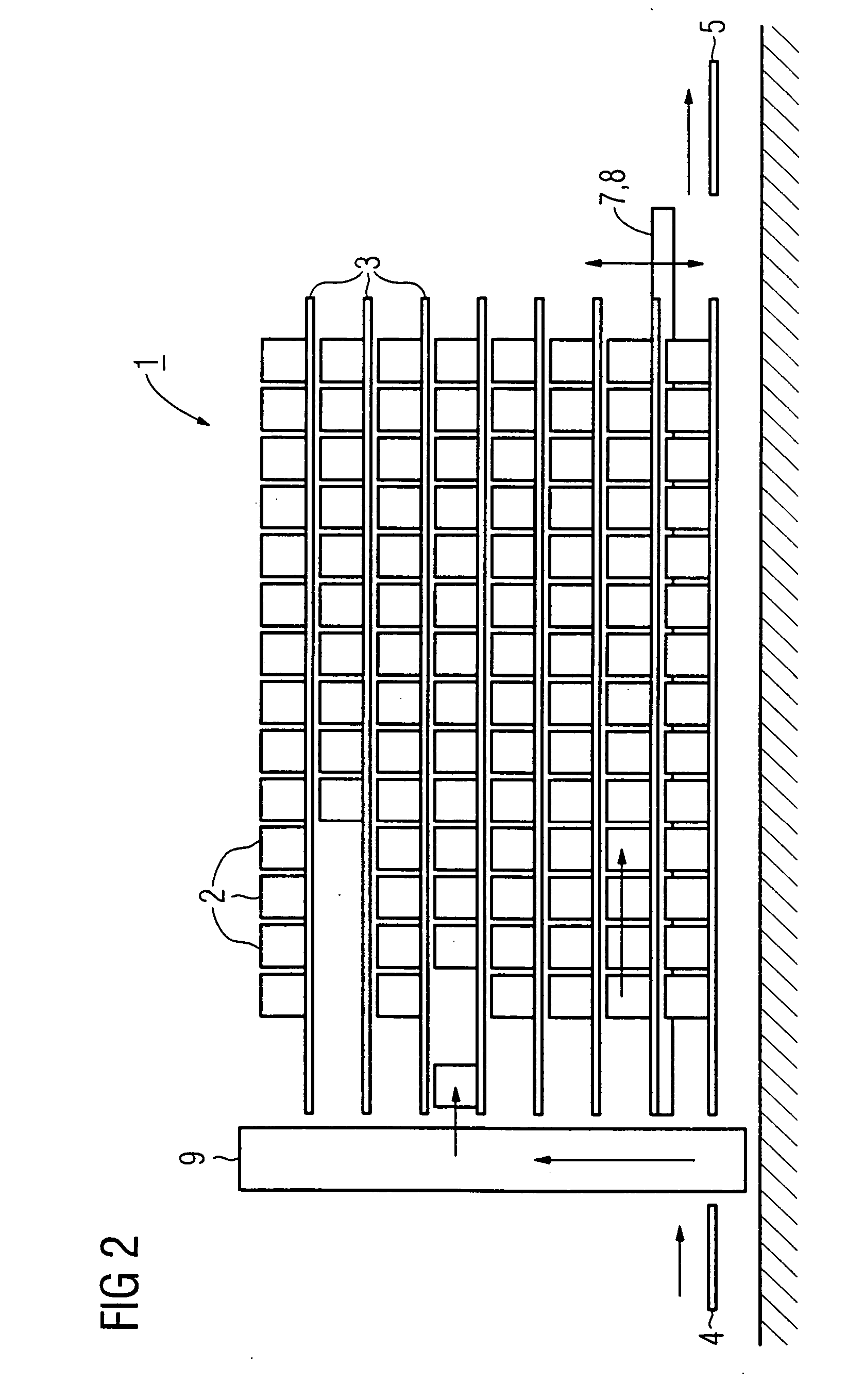
[0019] The placing of load carriers into the store may be carried out by means of a lifting device arranged on the end side of the rack. This enables all of the rack levels to be serviced independently of the one or more load suspension means and may be provided in combination with an arrangement of the storage points of the rack levels on accumulating conveyors on which the originally adopted storage place is displaced as time passes in accordance with the conveying movement. The actual storage location within a rack level can easily be updated by the electronic controlling means of the system according to the invention by recognition of the particular path of movement of the accumulating conveyor, with the result that the travel data required for the load suspension means in the case of removal can readily be made available.

Problems solved by technology

In the case of extensive orders, a single load carrier is frequently insufficient for this, and a plurality of load carriers are required.
A comparatively high throughput capacity is characteristic of this type of sequencing tower; by contrast, however, the storage capacity available for temporary storage is very restricted, thus requiring a correspondingly large number of these devices which are costly with regard to investment costs.
By contrast, limitations are to be seen with regard to the throughput capacity.

Method used


Image

  • Apparatus for forming a sequence of load carriers by means of a temporary store, and method for temporary storage
  • Apparatus for forming a sequence of load carriers by means of a temporary store, and method for temporary storage
  • Apparatus for forming a sequence of load carriers by means of a temporary store, and method for temporary storage

Examples


Embodiment Construction

[0025] The exemplary embodiment, illustrated in three views in FIGS. 1-3, for the invention shows a rack 1 which comprises two units 1a, 1b which are constructed identically and lie opposite each other at a distance in parallel and in a mirror-inverted manner leaving a storage aisle. Each rack unit 1a, 1b is assigned a respective conveying unit 4a, 4b of a feed-in device 4 which is arranged on the left end side of the rack 1 and serves to feed in load carriers 2 to be newly temporarily stored at a free storage point of one of the rack levels 3 of the rack 1. The individual rack levels 3 may be designed as accumulating conveyors, so that the filling of the storage points can take place in an extremely simple and effective manner via a lifting station 9 which is arranged directly between the feed-in device 4 and the end side of the rack 1.

[0026] Corresponding to the division of the feed-in device 4 and of the rack 1 into two units in each case, the lifting station 9 is also divided i...


PUM


Abstract

In order to permit a temporary storage with a simultaneously high number of storage places and high throughput capacity, a rack (1) which may include mutually opposite rack units (1a, 1b), in the rack aisle of which a vertically movable lifting bar (7) is arranged. Two load suspension means (6a, 6b) may be provided for removing the load carriers (2) and are movable horizontally at the lifting bar (7). Removed load carriers (2) are deposited in the respectively desired sequence on a conveyor (8), which is connected fixedly to the lifting bar (7) and the conveying direction of which can be reversed, and may then be delivered batchwise onto a removal device (5) for further transportation. The rack levels (3) of the rack (1) may be accumulating conveyors, with it being possible for the load carriers (2) to be placed into the store from the end side of the rack (1) via a lifting device (9a, 9b) without using the load suspension means (6a, 6b). The method and apparatus may be used, by way of example, to facilitate the packing of goods order picked on load carriers (2), the load carriers (2) belonging to an order are first of all collected in a temporary store and are then conveyed for dispatch in a predetermined sequence favorable for packing.

Description

BACKGROUND OF THE INVENTION [0001] The invention relates to an apparatus for temporary storage of load carriers by means of a temporary store, designed as a rack, with a plurality of rack levels and to a method for temporary storage of load carriers. [0002] During the order picking of orders, the goods belonging to an order are frequently collected on load carriers which usually have a uniform shape and are designed, for example, as box-shaped containers. In the case of extensive orders, a single load carrier is frequently insufficient for this, and a plurality of load carriers are required. The collecting of the goods is frequently undertaken by different order pickers at different times at different order picker locations. The filled load carriers which belong to a common order are therefore available at different times for assembling together by dispatch. However, an order dispatch sequence requires not only the complete provision of all items of an order, but as far as possible ...

Claims


Application Information

Patent Timeline
IPC IPC(8): B65G65/00
CPCB65G1/0435B65G1/1376B65G1/10B65G1/06
Inventor SUESS, HEIKO
Owner SIEMENS AG
Learn More