Semiconductor device structure and method for reducing hot carrier effect of MOS transistor

a technology of mos transistor and semiconductor device, which is applied in the direction of semiconductor devices, electrical equipment, transistors, etc., can solve the problems of reducing reliability and hot carrier effect affecting the operation of the transistor, etc., and achieves the effect of increasing the lifetime of the device and reducing the hat carrier

Active Publication Date: 2006-11-02
UNITED MICROELECTRONICS CORP
View PDF4 Cites 3 Cited by
  • Summary
  • Abstract
  • Description
  • Claims
  • Application Information

AI Technical Summary

Benefits of technology

[0006] Accordingly, one object of this invention is to provide a semiconductor device structur

Problems solved by technology

However, such a dimension reduction causes a hot carrier effect affecting the operation of the transistor.
A part of the hot e

Method used


Image

  • Semiconductor device structure and method for reducing hot carrier effect of MOS transistor
  • Semiconductor device structure and method for reducing hot carrier effect of MOS transistor

Examples


examples

[0023] Examples A1-A2 and B1-B3 use an A-type chamber and a B-type chamber, respectively. The deposition parameters and the experiment result of each example are listed in Table 1.

TABLE 1ExampleA1B1B2RecipeHF (W)600 W170 W100 WLF (W)0150 W0SH4 (sccm)50060160NH3 (sccm)40000600N2 (sccm)16003000600PropertiesRefractive index2.222.052.2of filmSi—H ( / cm3)1.9 × 10226.2 × 10211.8 × 1022HCl (year)219120379

[0024] As indicated by Example A1, by turning off the LF power, the Si-rich SiN layer obtained has a higher silicon content and a higher refractive index. The hot carrier injection (HCl) index of the device obtained from Example A1 is 219 years.

[0025] Moreover, as indicated by Examples B1 and B2, the Si-rich SiN layer obtained from Example B2, in which the HF and LF powers are lowered at the same time, has a higher silicon content and a higher refractive index. By lowering the HF and LF powers at the same time in the SiN deposition, the HCl index of the device obtained from Example B2 is...


PUM


Abstract

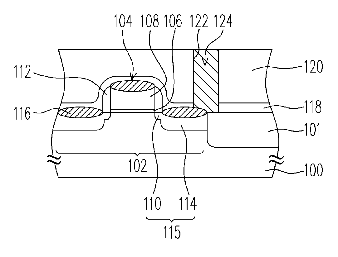
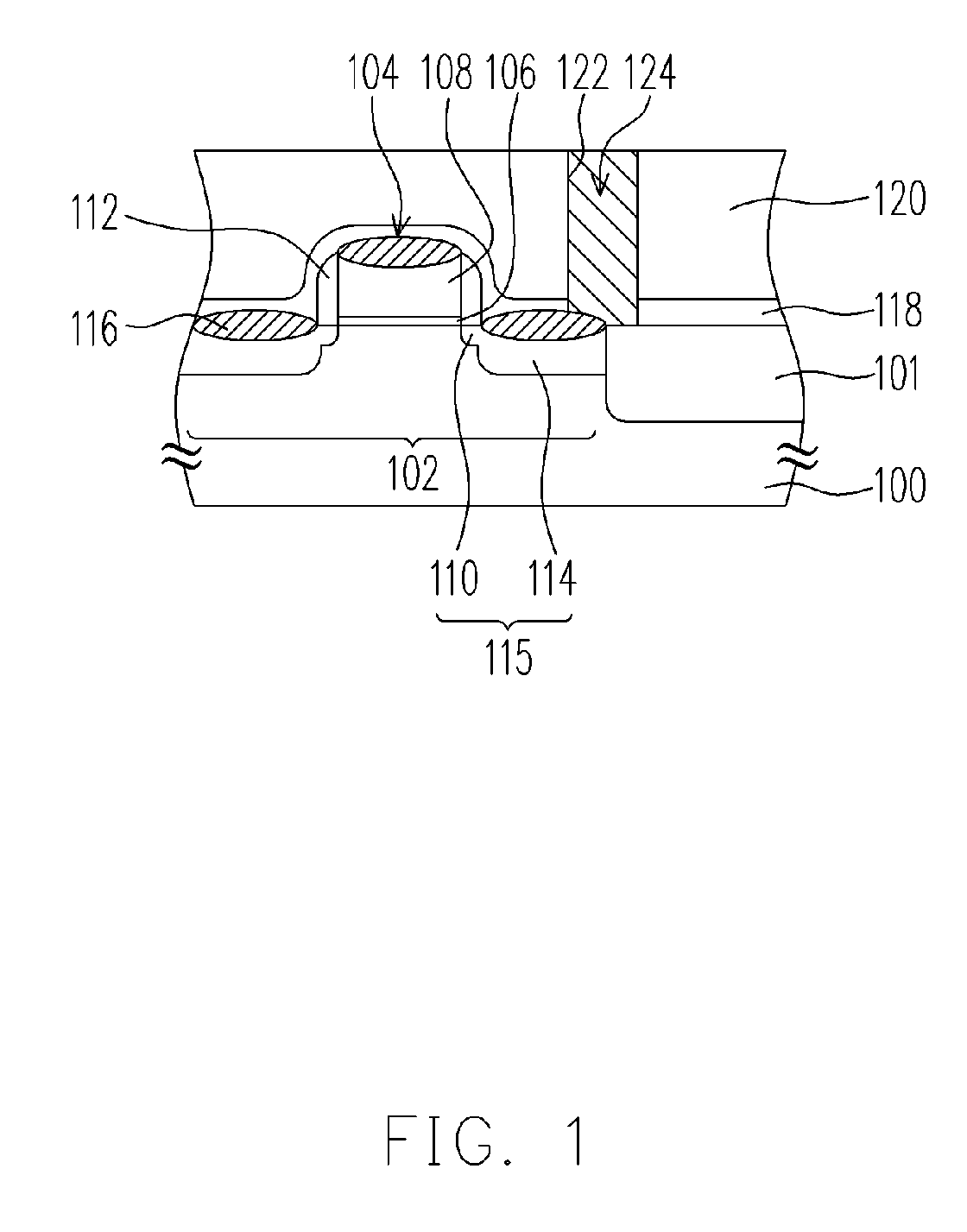
A semiconductor device structure is described, including a MOS transistor, a silicon-rich silicon nitride layer having a refractive index of about 2.00-2.30, and a dielectric layer. The silicon-rich silicon nitride layer is disposed between the MOS transistor and the dielectric layer, and covers the source/drain region, the spacer and the gate conductor of the MOS transistor.

Description

BACKGROUND OF THE INVENTION [0001] 1. Field of the Invention [0002] The present invention relates to a semiconductor device structure. More particularly, the present invention relates to a semiconductor device structure capable of reducing the hot carrier effect and a method for reducing the hot carrier effect of a metal-oxide-semiconductor (MOS) transistor. [0003] 2. Description of the Related Art [0004] MOS transistors are the most important elements in various electronic products. To compactify the electronic products, the dimensions of a MOS transistor have to be reduced. However, such a dimension reduction causes a hot carrier effect affecting the operation of the transistor. More specifically, when the channel length is decreased but the voltage applied is fixed, not only the operation speed of the transistor is increased, but also the lateral electric field in the channel is increased. Thereby, the energy of the channel electrons is increased, while the channel electrons near...

Claims


Application Information

Patent Timeline
IPC IPC(8): H01L21/4763H01L29/76H01L29/94H01L31/00
CPCH01L29/665H01L29/7843H01L29/7833H01L29/6659
Inventor CHEN, MIN-HSIANHSIEH, CHING-HSING
Owner UNITED MICROELECTRONICS CORP
Why Eureka
Try Eureka