Automated manipulation of imaging device field of view based on tracked medical device position

a technology of imaging device and tracking position, which is applied in the direction of catheters, applications, diagnostic recording/measuring, etc., can solve the problems of difficult for physicians to visualize anatomy features as a reference for navigation, limited use of fluoroscopy, and difficulty in locating catheter features, etc., to facilitate tissue imaging, facilitate tissue imaging, and reduce radiation exposure

Active Publication Date: 2006-11-02
BOSTON SCI SCIMED INC
View PDF18 Cites 84 Cited by
  • Summary
  • Abstract
  • Description
  • Claims
  • Application Information

AI Technical Summary

Benefits of technology

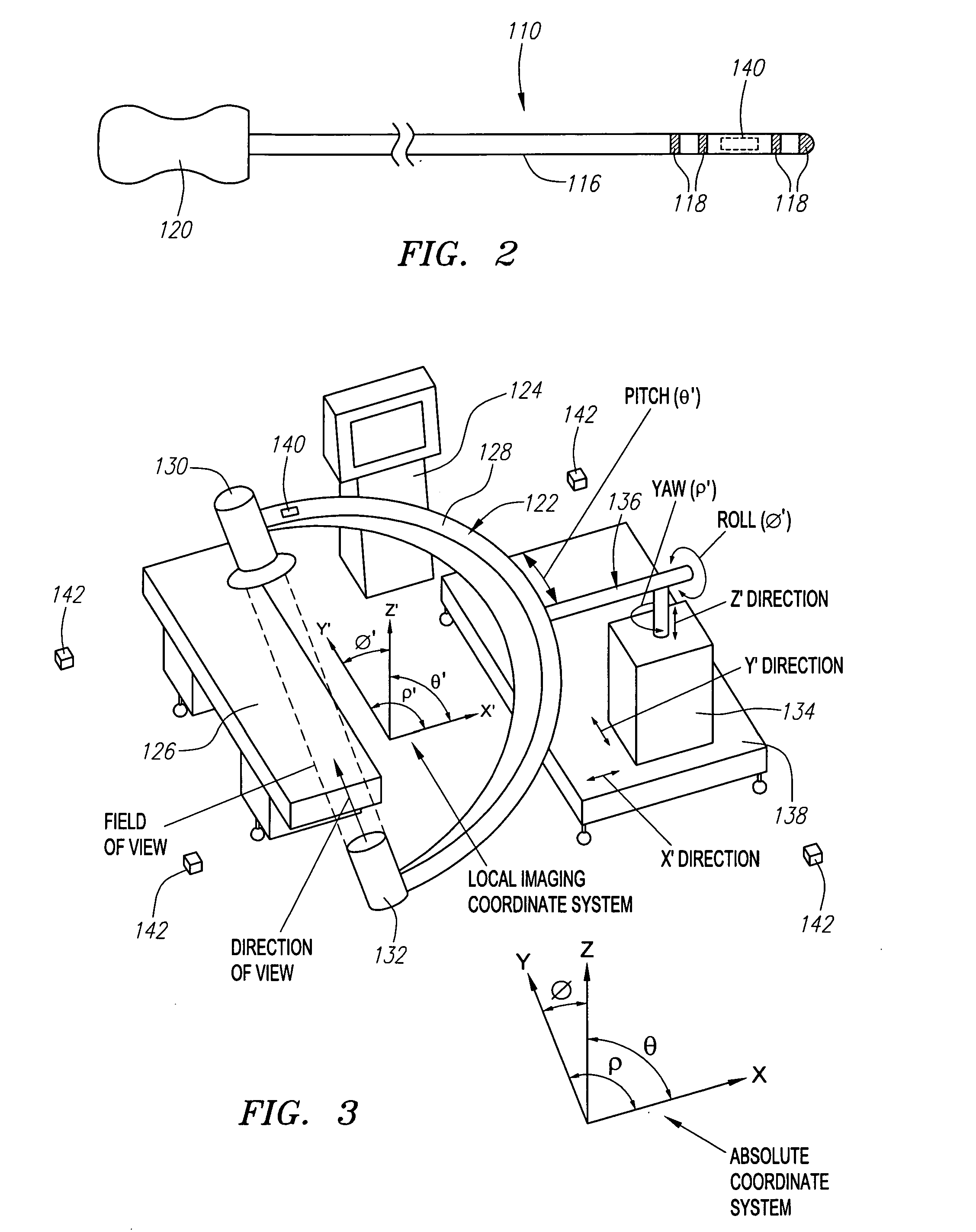
[0012] In one method, the patient is imaged along a direction of view that is oriented at an angle perpendicular to the axis of the medical device portion. This may be useful, e.g., for more accurately measuring the length of objects within the field of view. In another method, the patient is imaged along a direction of view that is oriented at an angle parallel to the axis of the medical device portion. This may be useful, e.g., for more accurately measuring the diameter of the channel (e.g., blood vessel) in which the medical device is disposed. In one method, the field of view position is adjusted mechanically, e.g., when using fluoroscopy. However, the field of view position may alternatively be adjusted electronically, e.g., when using electronically-steered ultrasound.
[0013] Although the present inventions should not be so limited in their broadest aspects, the automatic adjustment of the field of view position obviates, or at least minimizes, manual adjustment of the imaging modality, thereby decreasing the procedure time, and reducing radiation exposure. Also, because the field of view is automatically adjusted to cover only the relevant tissue, the radiation footprint may be reduced, thereby further decreasing radiation exposure and potentially reducing the cost of the imaging device. An optional method comprises activating the imaging based on the detected position of the medical device portion. In this manner, imaging may be performed only when needed, e.g., when the medical device is moving or becomes unstable, thereby further decreasing radiation exposure.
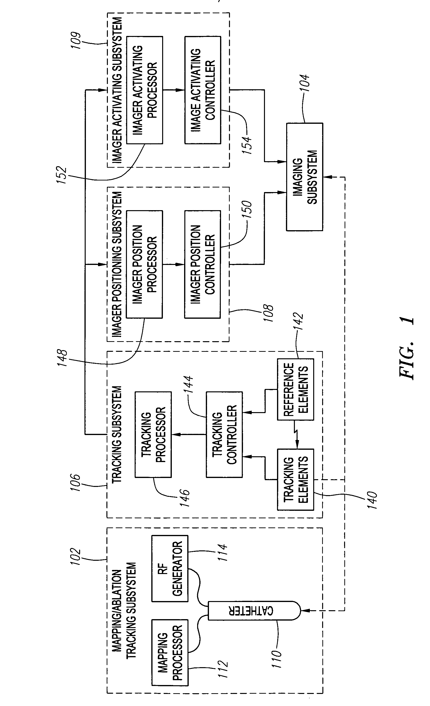
[0014] In accordance with a second aspect of the present inventions, a medical navigation system is provided. The system comprises a tissue imaging device having a field of view, an intrabody medical device, a tracking subsystem (e.g., a non-fluoroscopic navigation system) configured for detecting a position (e.g., a location and / or orientation) of the medical device, and an imager positioning subsystem configured for adjusting a position of the field of view (e.g., mechanically and / or electronically) relative to a patient based on the detected position of the medical device. The imager positioning subsystem can be configured for continuously adjusting the field of view, or intermittently adjusting the field of view position (e.g., on-demand). As with the previously described method, the adjustment of the field of view based on the position of the medical device facilitates the imaging of only relevant tissue.
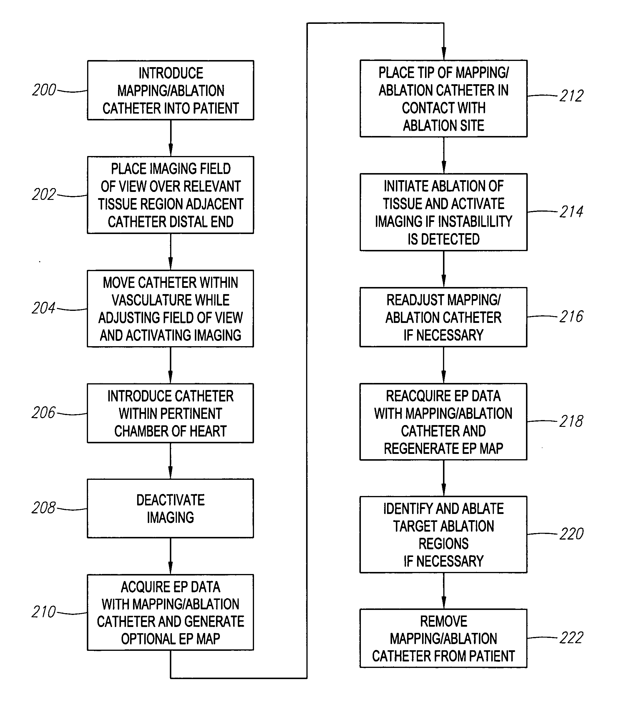
[0018] The method further comprises automatically activating imaging of the patient based on the detected relative position. Although the present inventions should not be so limited in their broadest aspects, the automatic activation of the imaging facilitates the imaging of tissue only during relevant times, thereby reducing radiation exposure. In one method, instability / stability of the medical device is detected, in which case, the imaging is automatically activated when the medical device is unstable, and deactivated when the medical device is stable. Another method comprises ablating tissue with the medical device, and performing position detection and imaging activation steps during the tissue ablation step. In this manner, medical personnel can be made aware of inadvertent movement of the medical device via the image, and can correct any displacement of the medical device from the ablation site. An optional method comprises automatically adjusting a position of a field of view of the imaging relative to the patient based on the detected position. In this manner, the method not only facilitates imaging of the tissue region during relevant times, it also facilitates imaging of only the relevant tissue.
[0019] In accordance with a fifth aspect of the present inventions an imaging system is provided. The system comprises a tissue imaging device, an intrabody medical device, a tracking subsystem configured for detecting a position (e.g., location and / or orientation) of the medical device, and an imager activating subsystem configured for comparing the detected medical device position to a reference position (e.g., a previously detected position of the medical device or a position within a desired path), and activating the imaging device based on the comparison. As with the previously described method, the activation of the imaging device based on the position of the medical device facilitates the imaging of tissue only during relevant times.
[0020] In one system, the imager activating subsystem detects the instability / stability of the medical device based on the comparison, in which case, it can activate imaging when the medical device is unstable, and deactivate imaging when the medical device is stable. If the medical device carries a tissue ablation element, the stability / instability of the medical device can be detected during the ablation process, as discussed in the previous method above. In an optional embodiment, the system comprises an imager positioning subsystem configured for automatically adjusting a position of a field of view of the imaging device relative to a patient based on the detected medical device position. As previously discussed above, this provides the added advantage of limiting the imaging to only relevant tissue.

Problems solved by technology

This is because the use of fluoroscopy in locating catheters is somewhat limited in that the physician is only able to visualize the catheter and surrounding tissues in two dimensions.
In addition, fluoroscopy does not image soft tissues, making it difficult for the physician to visualize features of the anatomy as a reference for the navigation.
The use of fluoroscopy is also limited in that it poses the danger of exposing the patient and laboratory personnel to harmful doses of radiation.
Unfortunately, manual adjustment of the position of an imaging system relative to the patient can be time consuming, difficult, labor intensive, imprecise, and inconvenient.
Furthermore, because it may be necessary to visualize a real-time image to determine how to properly adjust the position of the imaging system, this manual adjustment process can lead to prolonged operation of the imaging system.
This, in turn, may lead to increased radiation exposure (in the case of fluoroscopy) to the patient and / or medical personnel and may lead to premature failure or degradation of the imaging system due to extended operational time (i.e., components may wear out sooner).
Manual adjustment may also not allow the degree of positional accuracy that may be desired.
However, because it is often difficult to predict when fluoroscopic images of the relevant region should be generated, e.g., when a catheter becomes unstable, the fluoroscope may not always be operated when it is most needed.

Method used


Image

  • Automated manipulation of imaging device field of view based on tracked medical device position
  • Automated manipulation of imaging device field of view based on tracked medical device position
  • Automated manipulation of imaging device field of view based on tracked medical device position

Examples


Embodiment Construction

[0033] Referring to FIG. 1, an exemplary medical navigation system 100 constructed in accordance with the present inventions will be described. The navigation system 100 is particularly suited for intravascularly navigating catheters used to perform intracardiac electrophysiology procedures, but can be used for navigating other catheters, such as angiograph and angioplasty catheters, as well as other medical devices, within a patient's body, including non-vascular medical devices.

[0034] The medical system 100 generally comprises (1) a mapping / ablation subsystem 102 for mapping and ablating tissue within the heart; (2) an imaging subsystem 104 for generating medical images of select regions of the patient's body; (3) a tracking subsystem 106 for tracking movable objects, such as catheters and the imaging components of the imaging subsystem 104; (4) an imager positioning subsystem 108 for mechanically manipulating the imaging subsystem 104 based on tracking information acquired from ...


PUM


Abstract

Methods and systems for navigating medical devices are provided. A patient is imaged while a medical device is moved within the patient. A position (e.g., a location and / or orientation) of the moving medical device is detected within a coordinate system (e.g., a three-dimensional coordinate system), a position of the imaging field of view relative to the patient is adjusted based on the detected medical device position, such that the relevant tissue region of the patient is within the field of view. For example, the field of view can be centered over the medical device or centered just distal to the medical device portion. The direction of view may be oriented at an angle perpendicular to the axis of the medical device, e.g., for more accurately measuring the length of objects within the field of view, or oriented at an angle parallel to the axis of the medical device portion, e.g., for more accurately measuring the diameter of the channel (e.g., blood vessel) in which the medical device is disposed.

Description

FIELD OF THE INVENTION [0001] The present inventions generally relate to systems and methods for navigating medical probes within anatomical organs or other anatomical structures. BACKGROUND OF THE INVENTION [0002] It is often necessary or desirable to determine the location of a medical probe relative to a location of interest within three-dimensional space. In many procedures, such as interventional cardiac electrophysiology therapy, it is important for the physician to know the location of a probe, such as a catheter (especially, a therapeutic catheter), relative to the patient's internal anatomy. During these procedures, a physician, e.g., steers an electrophysiology (EP) mapping catheter through a main vein or artery into the interior region of the heart that is to be treated. The physician then determines the source of the cardiac rhythm disturbance (i.e., the targeted cardiac tissue) by placing mapping elements carried by the catheter into contact with the heart tissue, and o...

Claims


Application Information

Patent Timeline
Patent Type & Authority Applications(United States)
IPC IPC(8): A61M25/00
CPCA61B5/06A61B6/12A61B6/4441A61B6/487A61B2019/5454A61B19/5244A61B2019/5238A61B2019/5251A61B2019/5259A61B19/52A61B90/36A61B34/20A61B2090/376A61B2034/2051A61B2034/2059A61B2090/3954A61B5/062A61B5/063A61B5/068
Inventor MCGEE, DAVID L.
Owner BOSTON SCI SCIMED INC
Why Eureka
Try Eureka