
Articulating radio frequency probe handle

a radio frequency probe and handle technology, applied in the field of articulating radio frequency probe handle, can solve the problems of compounding problems, little maneuvering room for inserting, moving or adjusting the probe, and inability to observe without assistance, and achieve the effect of convenient manipulation

Inactive Publication Date: 2006-11-02
BOSTON SCI SCIMED INC
View PDF21 Cites 7 Cited by
  • Summary
  • Abstract
  • Description
  • Claims
  • Application Information

AI Technical Summary

Benefits of technology

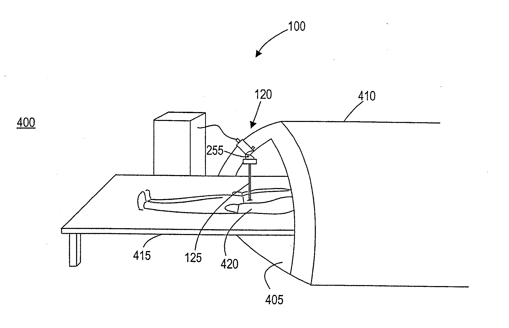
The present invention provides a medical probe assembly for ablating tissue that includes an elongated rigid probe with a bendable handle assembly. The handle assembly can be bent to shorten its length, making it easier to manipulate in confined spaces such as a CT scanner or MRI chamber. The handle assembly can be locked in a rigid position or unlocked to allow for flexibility. The handle assembly can be used to selectively deploy and retract the ablative elements using an actuator. The medical probe assembly can be easily inserted into a patient and the handle bent prior to placement in a confined space. The method of using the medical probe assembly allows for easy manipulation in confined spaces and can be observed using computerized axial tomography or magnetic resonance imaging.

Problems solved by technology

Since the ablation is occurring internally, unaided observation is not possible.
Unfortunately, the more popular CT and MRI imaging techniques require that the patient lie inside a relatively small tubular chamber.
In such close quarters there is very little maneuvering room to insert and move or adjust the probe.
This problem is compounded if the patient is obese, or if the target region for the RF energy is near the surface of the body, such as when the target region is a shallow sub-dermal lesion.
Since conventional probes have rigid and relatively long handles, they are often unsatisfactory for performing an ablation surgery while simultaneously monitoring its progress using CT or MRI imaging techniques.
Moreover, given the equipment that must be housed inside the handle, and the fact that the handle must fit comfortably into the surgeon's hand, it is unrealistic to attempt to solve the problem by shortening the handle enough so that it can be used inside the monitoring chamber.

Method used


Image

  • Articulating radio frequency probe handle
  • Articulating radio frequency probe handle
  • Articulating radio frequency probe handle

Examples


Embodiment Construction

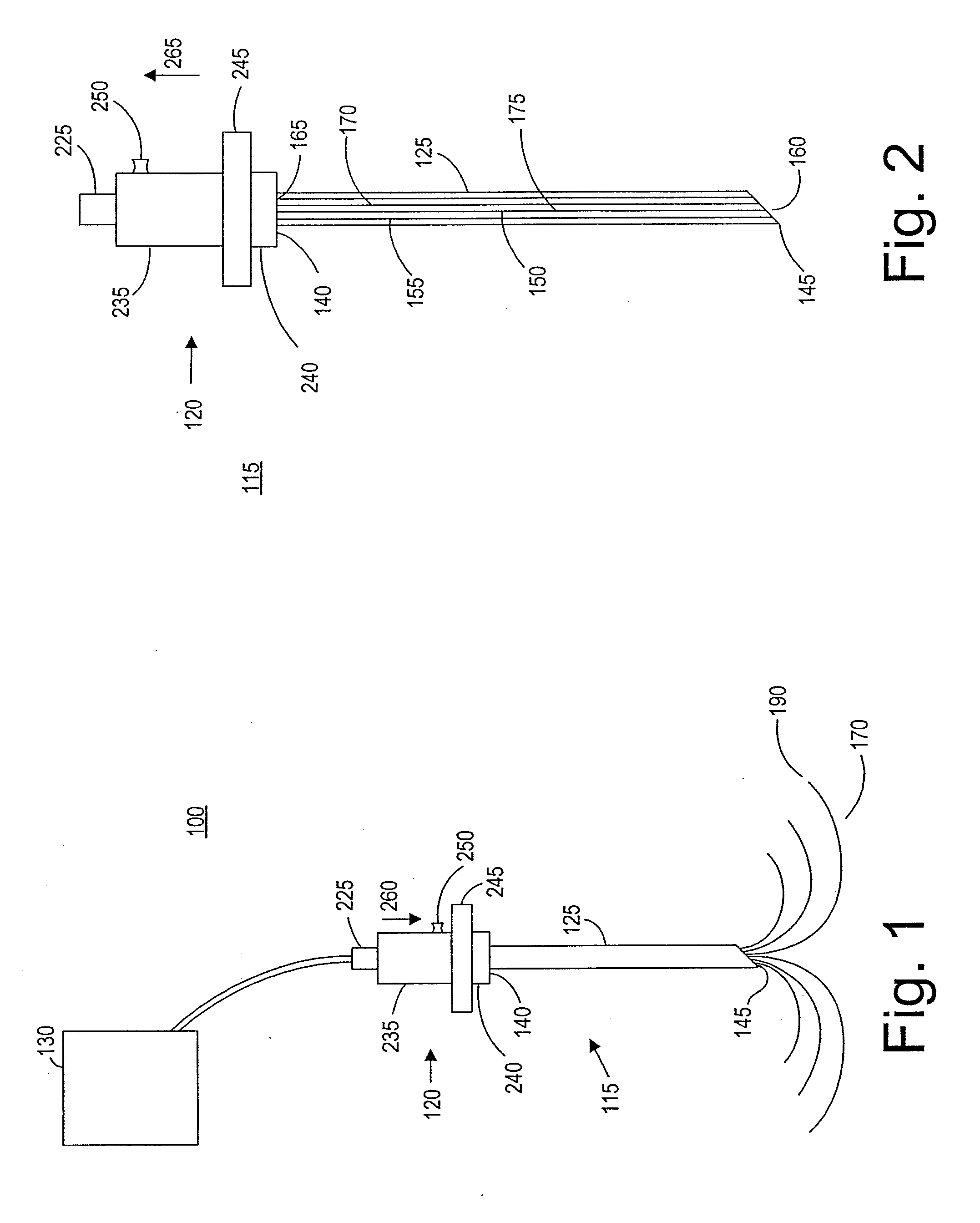
[0033]FIG. 1 illustrates a tissue ablation system 100 constructed in accordance with a preferred embodiment of the present invention. The tissue ablation system 100 generally comprises an ablation probe assembly 115, which is configured for introduction into the body of a patient to ablate target tissue such as a tumor, and a radio frequency (RF) generator 130 configured for supplying RF energy to the probe assembly 115 in a controlled manner.

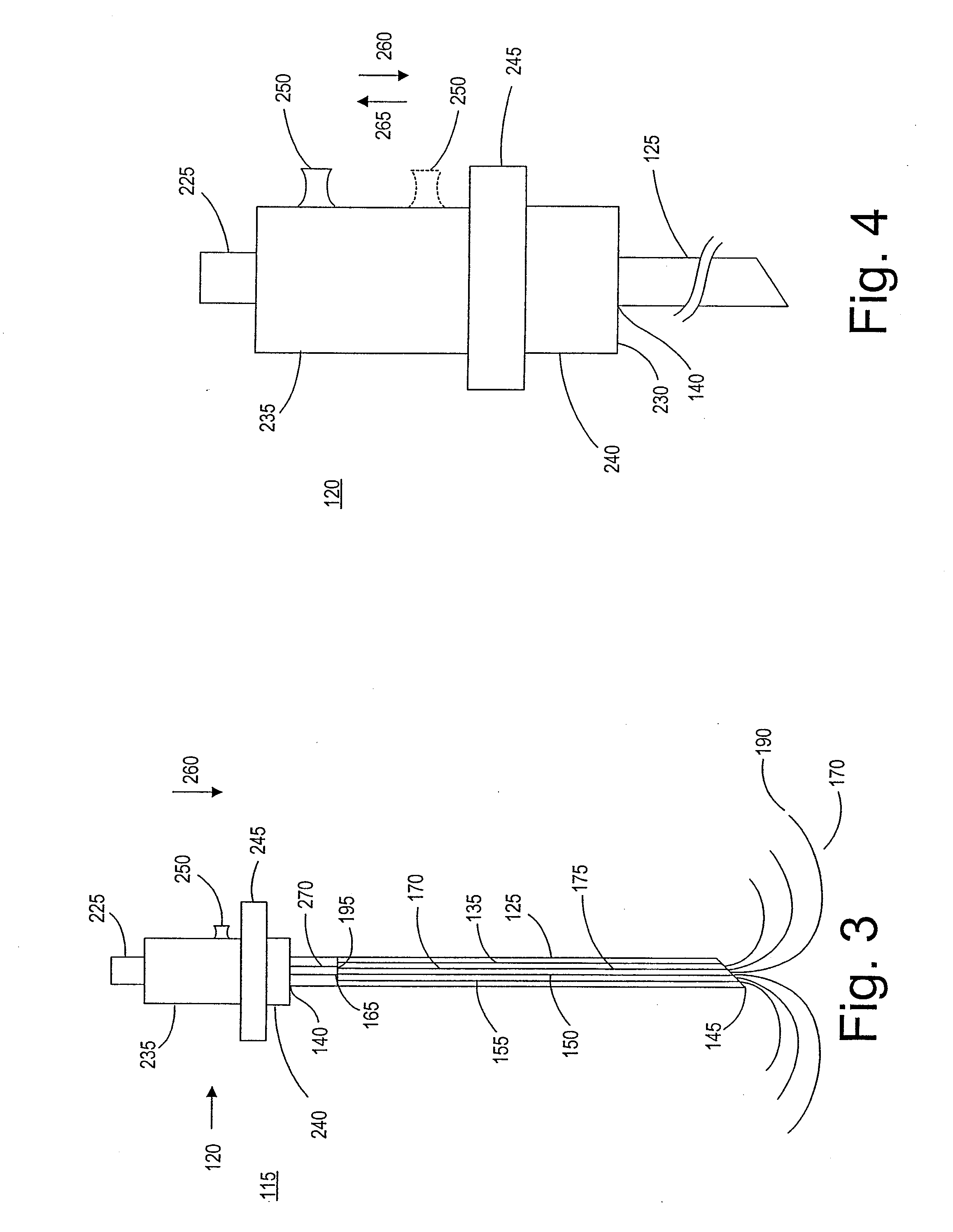
[0034] Referring specifically to FIGS. 2 and 3, the probe assembly 115 generally comprises a handle assembly 120, an elongated cannula 125, and an inner probe 135 slideably disposed within the cannula 125. The handle assembly 120 is mounted to the cannula 125 and includes a generator connector 225 that can be electrically coupled to the RF generator 130. As will be described in further detail below, the cannula 125 serves to deliver the active portion of the inner probe 135 to the target tissue. The cannula 125 has a proximal end 140, a distal...


PUM


Abstract

A medical probe assembly and method for ablating tissue using radio frequency energy. The medical probe assembly includes an elongated shaft, a needle electrode array, and a hinged handle. The handle has a collar, which when in the up position covers the hinge so that the device can be used as a conventional medical probe. When the collar is in the down position the hinge is exposed, and the handle can be bent to reduce its overall height. With this reduced height the probe can be used while a patient is lying in a CT scanner or an MRI chamber. Therefore, the surgeon can monitor the ablation during the procedure, and thus avoid unnecessary damage to the surrounding healthy tissue on the one hand, and insufficient ablation of the diseased tissue on the other hand. An alternate embodiment uses a flexible handle instead of a hinged one.

Description

CROSS REFERENCE TO RELATED APPLICATION [0001] This application is a continuation of co-pending U.S. application Ser. No. 10 / 345,669, filed Jan. 15, 2003, the disclosure of which is hereby incorporated by reference.FIELD OF THE INVENTION [0002] The field of the present invention relates generally to the structure and use of radio frequency (RF), electro-surgical probes for the treatment of tissue disorders such as tumors and lesions, and more particularly, to handle assemblies for electro-surgical probes. BACKGROUND OF THE INVENTION [0003] Radio frequency (RF) energy can be used to ablate solid tissue, thus inducing localized tissue necrosis. RF energy is particularly useful in this capacity, for inducing necrosis in sub-dermal lesions and tumors such as those found in cancers of the liver, stomach, kidney, lung, bowel, and pancreas. The conventional delivery system for this sort of treatment is an electro-surgical probe, and one benefit to using such a probe is that it is much less ...

Claims


Application Information

Patent Timeline
Patent Type & Authority Applications(United States)
IPC IPC(8): A61B18/14A61B19/00
CPCA61B18/1477A61B18/148A61B2019/5238A61B2018/143A61B2019/5236A61B2018/1425A61B2090/376A61B2090/374
Inventor BOURNE, GEORGERIOUX, ROBERT
Owner BOSTON SCI SCIMED INC
Learn More