[0012] The definition file of the present invention includes a plurality of parallel descriptions that respectively define a plurality of parallel processes that are performed independently and in synchronization. Accordingly, to execute the parallel
processing defined by the definition file of the present invention, a
program counter showing a temporal order is not required. In addition, in the definition file, an
algorithm can be defined by including a parallel description showing or indicating a parallel process into which output data the other parallel process is inputted. However, in parallel descriptions with variables, if the course or history of variables is not unambiguously determined, there is the possibility that the
algorithm will not be executed as intended. In a first parallel description showing a first parallel process including a plurality of data inputs, by understanding that data with a same latency from input into the system is inputted into the plurality of data inputs, variables are prevented from becoming unstable or uncertain. Accordingly, in the definition file, variables are unambiguously determined for each parallel description and therefore the algorithm can be correctly defined by the parallel descriptions. Also, in the definition file, the parallel processes according to the parallel descriptions are processes to be executed completely independently, the algorithm can be correctly described without extra processing such as synchronized communication and without solving timing problems with specifying hardware.
[0014] The definition file of the present invention includes a plurality of parallel descriptions, such an aspect is common to HDL, and therefore a
program counter is not required to execute parallel processes according to the plurality of parallel descriptions. Accordingly, the definition file can be said to describe hardware. In addition, the definition file includes a parallel description showing a parallel process with a
data input in which output data of another parallel process is inputted, and when there are a plurality of data inputs, the data inputted into such data inputs are determined unambiguously. Therefore, according to the present invention, it is possible to provide a
hardware description language that can define an algorithm correctly and understandably to the user. Additionally, even if the hardware is not understood in detail, the data are unambiguously inputted into the respective parallel processes, and therefore it is not necessary to have detailed information or knowledge of the hardware that actually performs the parallel processes. Accordingly, the definition file of the present invention is not dependent on the actual hardware and can describe hardware without a premise of specific hardware. For this reason, the definition file is an extremely general-purpose
hardware description language that is hardware independent. Therefore, the definition file is a tool or description suited to allowing a
software technician to easily design or generate an LSI or ASIC, and in particular, an LSI or ASIC including a large number of parallel processing elements.
[0015] In addition, when the plurality of parallel descriptions included in the definition file of the present invention are aligned in order of the latency of the data inputted therein, the plurality of parallel descriptions will be aligned in order of the time passing or history of the variables from inputting therein. In this state, the definition file has an aspect that is common to a program in which instructions are aligned in the order of execution. Accordingly, a
software technician can produce a definition file of the present invention with the same feeling as when producing a normal program. For this reason also, the definition file is a tool extremely suited to having a
software technician easily design and produce an LSI or ASIC. Also, according to the definition file of the present invention, it is possible to spatially lay out an algorithm using a plurality of elements capable of parallel processing, and therefore an application can be executed at high speed by effectively utilizing a system including a large number of elements that operate in parallel.
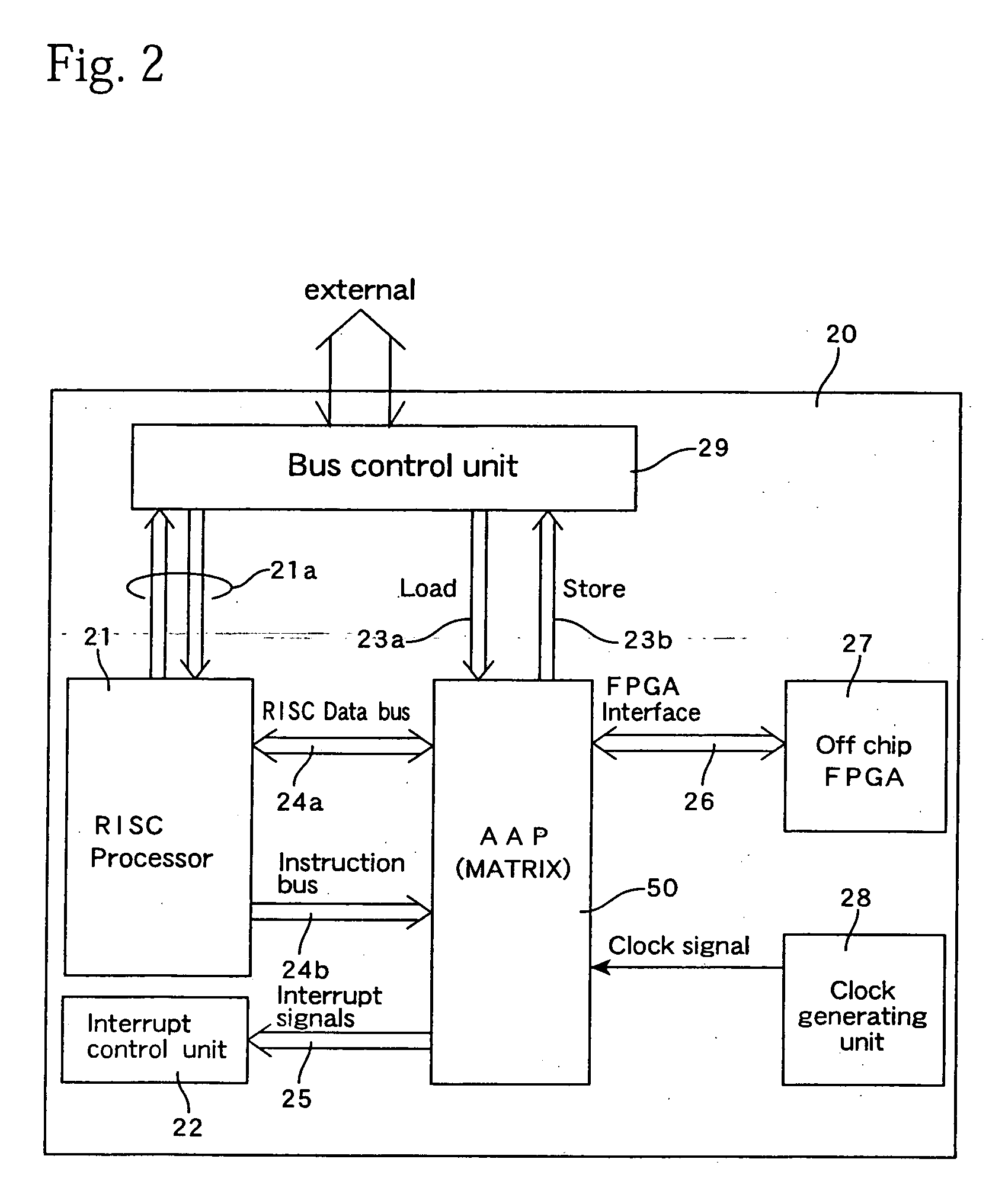
[0016] In the definition file of the present invention, for each parallel description, the latency of the input data should be the same, and the timing is adjusted. Accordingly, when hardware is formed according to a definition file, it is necessary to adjust the timing of the input data in units of parallel processes defined by the parallel descriptions. The elements for executing the parallel processes may be operation units that perform operations in bit units. In a parallel processing system where operation units with a certain degree of operation functioning, such as ALUs, are disposed in a matrix, it is possible to execute the parallel processes by mapping the parallel descriptions to one or a plurality of the operation units. To adjust the timing in units of the parallel descriptions, it is sufficient to add operation units for delaying, and therefore the definition file of the present invention is suited to describing a parallel processing system where a plurality of types of operation units are connected to realize a hardware configuration suited to an application. This means that by using the definition file of the present invention, it is possible to efficiently design and develop a parallel processing system, and also to simulate the same.
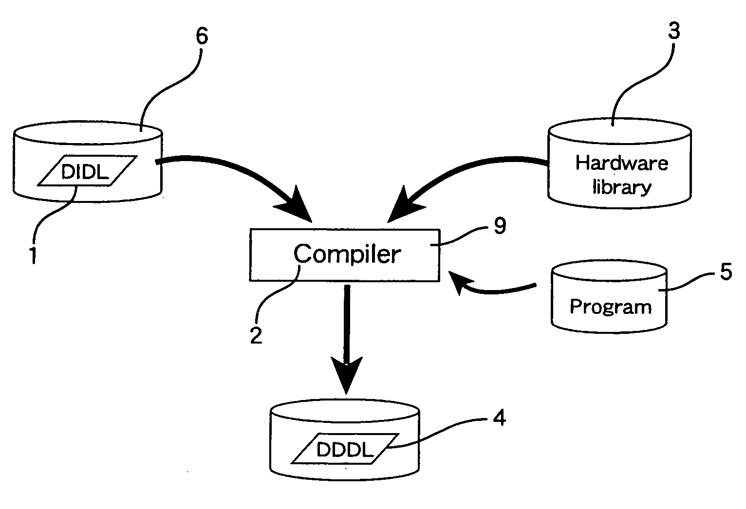
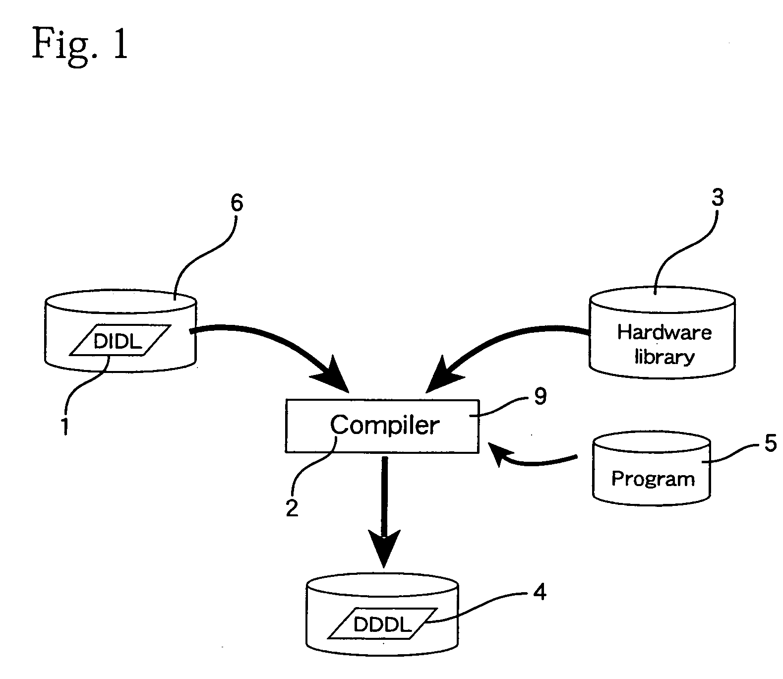
[0017] The definition file of the present invention can be provided having been recorded on a computer-readable recording medium, and based on the definition file, by using a computer, it is possible to form a parallel processing system including a plurality of types of elements that operate in parallel. That is, the plurality of parallel descriptions in the definition file include a first parallel description indicating a first parallel process with a plurality of data inputs including at least one
data input into which output data of another parallel process is inputted. By using a method for forming including a first step of generating, in accordance with the definition file and based on a hardware
library in which information on the plurality of types of elements is stored, hardware configuration information including circuit configurations (a hardware configuration) for executing the parallel processes defined by the parallel descriptions of the definition file and a second step of adding a
delay element to the hardware configuration information so that data with a same latency from input into the parallel processing system are inputted into the plurality of data inputs of the circuit configuration for executing a first parallel process, it is possible to generate information for configuring hardware in which an algorithm defined by the definition file is spatially laid out using a plurality of types of elements and therefore possible to form a parallel processing system that executes an application.
[0024] One of the plurality of types of operation units for the parallel processing system may include means for changing its process according to an input from the outside. Corresponding to this, the plurality of parallel descriptions should preferably include a parallel description describing parallel process where the processing content changes according to an input from the outside. It is possible to design a parallel processing system where the processing content can be changed even if the network or circuit wiring does not change. It is also possible to change the processing content of operation units together with the network or the circuit wiring, so that a reconfigurable parallel processing system can be designed even more flexibly.

