Method for monitoring a high resistivity reservoir rock formation

a reservoir rock and high resistivity technology, applied in the direction of measurement devices, acoustic wave reradiation, electric/magnetic detection for well-logging, etc., can solve the problems of production shut down, difficult to provide electrical energy for such a downhole transmitter antenna arranged near the actual production zone, and relatively complicated operation to reduce the antenna to the required depth in the well

Active Publication Date: 2006-11-16
DEN NORSKE STATS OLJESELSKAP AS
View PDF7 Cites 13 Cited by
  • Summary
  • Abstract
  • Description
  • Claims
  • Application Information

AI Technical Summary

Benefits of technology

[0013] As illustrated in FIG. 3c, one way of more efficiently transmitting an electro-magnetic signal that may propagate far into the high-resistivity formation may be using a toroidal coil transmitter antenna around the top of the casing. A toroidal coil antenna will generate a magnetic field H surrounding transversely to the casing and an electrical field directed normal to H. In FIG. 3c, the steel-lined well penetrates as a deviated well into the actual formation. Part of this wave will propagate along the steel-liner and thus continue propagating far in the horizontal direction, also beyond the extent of the conductive string, due to polarizing vertically in a low-conductive medium, in which few charges can be moved. A solenoidal transmitter coil will generate a transverse-electric (TE) field.

Problems solved by technology

A significant disadvantage of NO20020203 in case of arranging the antenna in the well is due to the fact that the operation to lower the antenna to the required depth in the well is relatively complicated.
Additionally, the operation of lowering the antenna inside the well most often requires that in such a well, in case of being a production well, production must be shut down temporarily.
Providing electrical energy for such a downhole transmitter antenna arranged near the actual production zone may be difficult, requiring long electrical supply lines.
For a well being drilled, the operation of arranging a downhole transmitter antenna would most probably be out of the question due to drilling economy and power supply problems.
Unfortunately, such short wavelengths suffer from very high attenuation.
Long wavelengths do not provide adequate resolution.

Method used


Image

  • Method for monitoring a high resistivity reservoir rock formation
  • Method for monitoring a high resistivity reservoir rock formation
  • Method for monitoring a high resistivity reservoir rock formation

Examples


Embodiment Construction

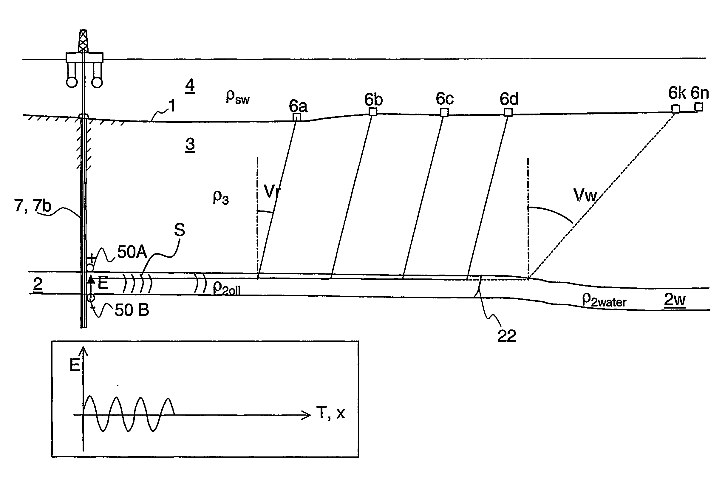
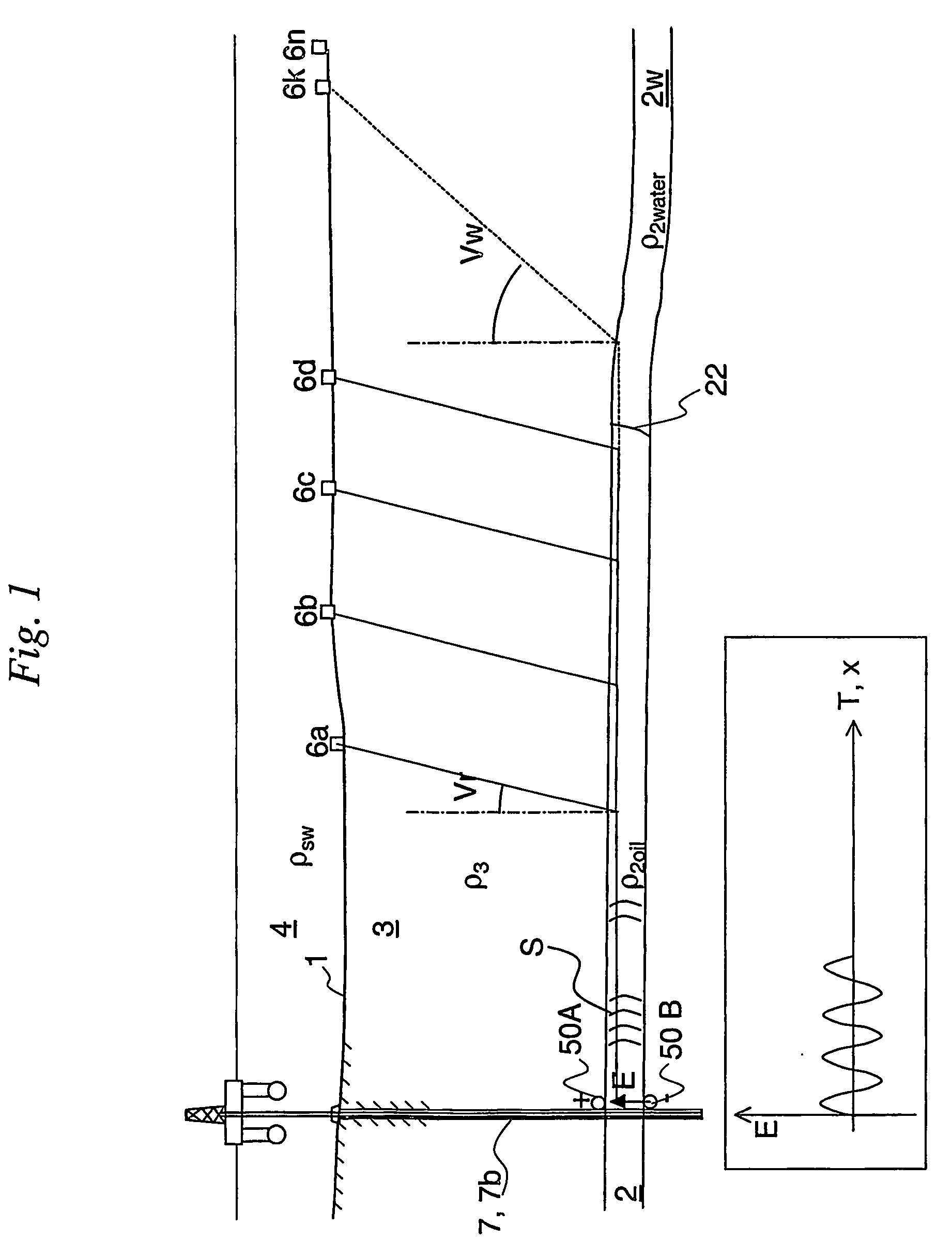
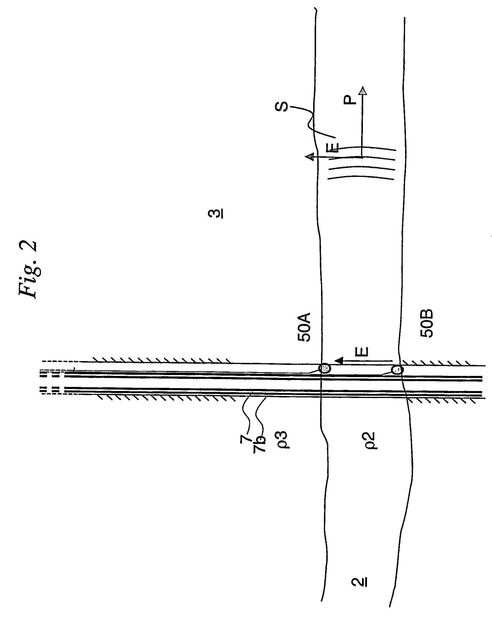
[0043]FIG. 1 illustrates a situation in which an electromagnetic transmitter's 5 antenna 50 is arranged in a borehole 7b through low-resistivity formations 3, and in which the borehole 7b also penetrates a high-resistivity petroleum fluid bearing formation 2. The antenna 50 is arranged at the outside of a conductive casing 7 for transmitting an electromagnetic signal S into the high-resistivity formation 2. As the electromagnetic waves propagate through the formations, eventually refracted electromagnetic waves are received on the surface 1 of the overburden geological formations 3. The surface 1 may be a seafloor or a land surface. The surface may, in the method of this method, not be the sea surface except for rather shallow applications, due to severe seawater attenuation of EM signals. A separation line 22 in the fluid bearing formation 2 indicates a transition from an oil-filled portion 2o of the high-resistivity formation 2 and a water-filled lower-resistivity portion of the f...


PUM


Abstract

A method for monitoring a high-resistivity reservoir rock formation (2) below one or more less resistive formations (3), comprising the following steps: Transmitting an electromagnetic signal (S) propagating from near a seafloor or land surface (1) by means of an electromagnetic transmitter (5) powered by a voltage signal generator (G). The electromagnetic signal (S) propagates from the seafloor (1) and is guided along a conductive string (7) to the high-resistive formation (2), and propagates as a guided-wave electromagnetic signal (S2) at a relatively higher speed (V2) inside the high-resistivity formation (2) than a propagation speed (V3) in the less resistive formations (3). The guided-wave electromagnetic signal (S2) gives rise to an upward refracting electromagnetic signal (R3) having the relatively lower propagation speed (V3) in the less resistive formations (3) and having an exit angle nearer to the normal N to the interface between said high-resistivity formation (2) and the lower-resistivity formation (3), and gives rise to a steeply rising refraction wave front (F3). The refracted electromagnetic wave front (F3) comprising refracted electromagnetic signals (R3) is detected along an array of sensor antennas (6a, 6b, 6c, . . . , 6k, . . . , 6n) along the seafloor, the array having a direction away from the transmitter (5). In a preferred embodiment of the invention, the electromagnetic transmitter (5) comprises an antenna (50) transmitting the electromagnetic signal (S) to an upper end (70 U) of an electrically conductive string (7), e.g. a steel casing or liner, the upper end (70 U) being arranged near said seafloor (1).

Description

INTRODUCTION [0001] Petroleum bearing formations usually are of high resistivity (low conductivity) due to non-conductive oil or gas having replaced conductive salt-containing water (brine) in the pores of the rock. The resistivity normally is reduced as brine replaces oil or gas during production, or increases if brine is substituted or flushed by fresh water or gas. This difference in resistivity may be used for monitoring a reservoir during production, or for distinguishing between petroleum-bearing and brine-bearing parts of a formation. KNOWN ART [0002] Generating an electromagnetic signal from a towed antenna is used for exploring sedimentary seabed formations below the seafloor. A typical resistivity of seawater, ρsw, may be about 0.3 Ωm, which is rather conductive. Attenuation of electromagnetic wave propagation is thus very high. This high conductivity (or low resistivity) of the seawater prevents much of the EM signal that is transmitted from the towed antenna in the water...

Claims


Application Information

Patent Timeline
Patent Type & Authority Applications(United States)
IPC IPC(8): G01V3/00G01VG01V3/12G01V3/30
CPCG01V3/30Y02A90/30G01V3/12
Inventor JOHNSTAD, SVEIN ERLINGKONG, FAN-NIANWESTERDAHL, HARALD
Owner DEN NORSKE STATS OLJESELSKAP AS
Why Eureka
Try Eureka