Method for modifying surface of polymer substrate, method for forming plated film on polymer substrate, method for producing polymer member, and coating member

a technology a surface modification, which is applied in the direction of liquid/solution decomposition chemical coating, instruments, synthetic resin layered products, etc., can solve the problems of increased costs, difficult to form a desired pattern, and difficult to selectively and precisely modify a portion of the surface of a polymer substrate with the technologies disclosed, etc., to inhibit the diffusion of metal complex

Inactive Publication Date: 2006-11-16
HITACHT MAXELL LTD
View PDF0 Cites 122 Cited by
  • Summary
  • Abstract
  • Description
  • Claims
  • Application Information

AI Technical Summary

Benefits of technology

[0010] The present invention has been made in order to solve the above-mentioned problems, an object of the present invention is to provide a simpler method for selectively (partially) modifying a portion of the surface of a polymer substrate with a supercritical fluid, while also more precisely and finely modifying a portion of the surface of a polymer substrate, a method for forming a plated film on a polymer substrate, a method for producing a polymer member, and a coating member used therein.
[0110] According to the above-mentioned method for producing a polymer member of the present invention, in addition to selectively (partially) modifying a portion of the surface of a polymer substrate by an easier method, a polymer member can be obtained in which a portion of the surface of a polymer substrate is modified highly precisely and finely.

Problems solved by technology

However, it is difficult to selectively and precisely modifying a portion of the surface of a polymer substrate with the technologies disclosed in these documents.
In addition, in Japanese Patent Application Laid-open No. 2002-313750, there is the fear of the following problems occurring since a substance (solute) is dissolved in a supercritical fluid and sprayed onto a polymer substrate.
Consequently, in the technology described in Japanese Patent Application Laid-open No. 2002-313750, although the solute can be deposited on the surface of the polymer substrate, t the surface of the polymer substrate cannot be modified by permeating the solute into the polymer substrate together with the supercritical fluid permeating into the polymer substrate.
Moreover, in Japanese Patent Application Laid-open No. 2002-313750, although a method is disclosed for partially adhering a substance (metal complex) in a selected region of a substrate surface with a supercritical fluid, this method requires a process in which the mask is produced separately from the substrate, thereby resulting in the problem of increased costs.
In addition, in the method disclosed in Japanese Patent Application Laid-open No. 2002-313750, since a mask is only set on a substrate, a gap is formed between the mask and the substrate and a supercritical fluid penetrates into the gap, thereby resulting in the fear of it being difficult to form a desired pattern by adhering the substance (metal complex) to the substrate according to the pattern of holes provided in the mask.

Method used


Image

  • Method for modifying surface of polymer substrate, method for forming plated film on polymer substrate, method for producing polymer member, and coating member
  • Method for modifying surface of polymer substrate, method for forming plated film on polymer substrate, method for producing polymer member, and coating member
  • Method for modifying surface of polymer substrate, method for forming plated film on polymer substrate, method for producing polymer member, and coating member

Examples


example 1

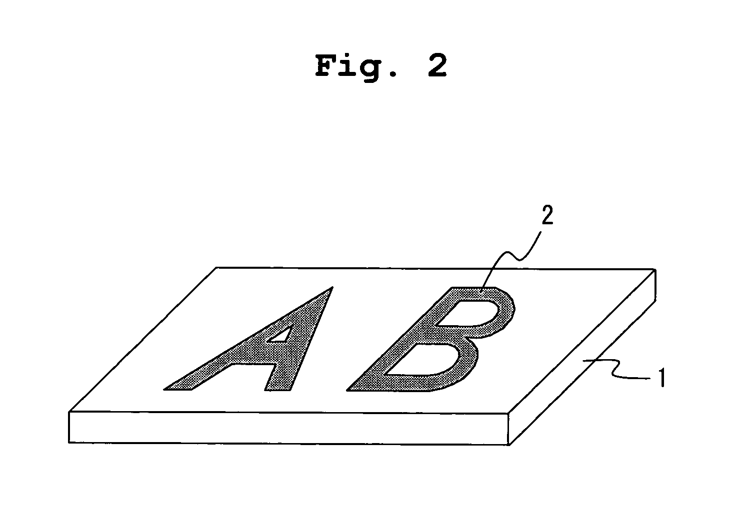
[0148] In Example 1, an explanation is provided of a method for carrying out surface modification by applying a dye 2 (permeating substance) to the surface of a polymer substrate 1 (polymer substrate) in a character pattern (“A” and “B”), and only allowing the dye 2 to permeate into the polymer substrate 1 only at that region as shown in FIG. 2.

High-Pressure Device Used in Surface Modification Method

[0149] First, an explanation will be provided of the high-pressure device used in the surface modification method of Example 1 with reference to FIG. 3. FIG. 3 is a schematic diagram showing a configuration of a high-pressure device used in the surface modification method of this example. As shown in FIG. 3, a high-pressure device 100 is mainly composed of a high-pressure container 11, a CO2 tank 12, a supercritical fluid regulator 13, and pipes 16a and 16b which connect these constituent elements.

[0150] As shown in FIG. 3, the high-pressure container 11 includes a container body 33, ...

example 2

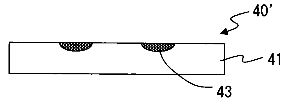
[0163] In Example 2, an example is explained in which the surface modification method of the present invention is applied to a plate used for biochemical analysis and so on referred to as micro TAS. The constitution of the micro TAS produced in this example is schematically shown in FIGS. 5A and 5B.

[0164] In the micro TAS 40 of this example, a pattern 42 of a permeating substance 43 as shown in FIG. 5A was formed on a polymer substrate 41. A polymer substrate made of polymethyl methacrylate resin and having a glass transition temperature Tg of about 100° C. (Asahi Chemical Industries, trade name: Delpet 560F) was used for the polymer substrate 41. Polyethyleneglycol (PEG) having an average molecular weight of about 1000 was used for the permeating substance 43 formed into the pattern 42. Namely, in this example, surface modification treatment was carried out which hydrophilized the surface region where the PEG 43 was applied by applying the PEG 43 to the surface of the polymer subs...

example 3

[0170] In Example 3, an example is explained in which the surface modification method of the present invention is applied to a micro TAS similarly as in Example 2. In this example, however, a preferable surface modification method is explained in the case of forming a finer permeating substance pattern in a polymer substrate as compared with that of Example 2.

[0171] Schematic diagrams showing a configuration of the micro TAS produced in this example are shown in FIGS. 6A and 6B. In the micro TAS 50 of this example, as shown in FIGS. 6A and 6B, a groove pattern 52 similar to the PEG pattern formed on the surface of the polymer substrate of the micro TAS produced in Example 2 was formed on the surface of a polymer substrate 51, and PEG 53 was applied into this groove pattern. In the micro TAS 50 of this example, the dimensions of the groove pattern 52 were as described below. The diameter of the circular portion 52a was 2 mm, the widths of the channel 52b and the branching channels 5...


PUM

PropertyMeasurementUnit
pressureaaaaaaaaaa
temperatureaaaaaaaaaa
pressureaaaaaaaaaa

Abstract

A method for modifying the surface of a polymer substrate is provided, which includes applying a permeating substance to predetermined region on the surface of the polymer substrate, and bringing a supercritical fluid into contact with the surface of the polymer substrate to which the permeating substance has been applied to cause the permeating substance to permeate into the polymer substrate. This method makes it possible to selectively (partially) modify a portion of the surface of the polymer substrate by an easier method.

Description

BACKGROUND OF THE INVENTION [0001] 1. Field of the Invention [0002] The present invention relates to a method for modifying a surface of a polymer substrate with a supercritical fluid, a method for forming a plated film on the surface of a polymer substrate, a method for producing a polymer member, and a coating member used in these methods. [0003] 2. Description of the Related Art [0004] Various processes have been proposed in recent years which use a supercritical fluid, which has permeability like a gas as well as which functions as a solution like a liquid, for the molding and processing of polymer substrates. For example, in Japanese Patent Application Laid-open No. 10-128783, since the supercritical fluid is able to lower the viscosity of a polymer substrate by acting as a plasticizer by permeating into a thermoplastic resin, a method for improving the fluidity and transferability of a polymer substrate during injection molding by utilizing this action of the supercritical flu...

Claims


Application Information

Patent Timeline
Patent Type & Authority Applications(United States)
IPC IPC(8): B05D5/00B05D3/00B05D1/40B32B27/00
CPCB05D3/101B05D7/02C23C18/1605C23C18/1608C23C18/1653Y10T428/24802C23C18/31H05K3/182H05K3/381H05K2203/087C23C18/2086Y10T428/31504H05K3/181C08J7/12C08J7/06B32B27/18
Inventor INOUE, KAZUKOSHIMAZAKI, KATSUSUKEYUSA, ATSUSHISUGIYAMA, TOSHINORI
Owner HITACHT MAXELL LTD
Why Eureka
Try Eureka