PIV high pressure infusion set

a high-pressure infusion and tubing technology, which is applied in the field of medical infusion sets, can solve the problems of inability to produce high-pressure tubing sets, inability to reduce the pressure of the infusion tube, and the inability to reduce the pressure of the infusion tube, and achieves the effect of easy production and cost-effectiveness

Inactive Publication Date: 2006-11-16
TRI STATE HOSPITAL SUPPLY
View PDF15 Cites 20 Cited by
  • Summary
  • Abstract
  • Description
  • Claims
  • Application Information

AI Technical Summary

Benefits of technology

[0004] The present invention provides a high-pressure tubing set that can withstand fluid pressures up to approximately 500 psi without bursting and / or leaking. The thinner-walled, softer durometer, chemically attacked portion of tubing connected to an end fitting is positioned inside of at least one circumferential reinforcement member to limit leak and burst in the area of the tubing bonded to the end fitting. This allows the tubing used to be of a softer (i.e., lower) durometer and thinner wall thickness, therefore making the high-pressure tubing set of suitable flexibility to be left on the patient as a general IV extension set before, during, and after high-pressure usages such as procedures performed in radiology units. The high-pressure tubing set of the present invention can be assembled using conventional solvent bonding technology, making the high-pressure tubing set cost-effective and easy to produce.
[0005] More particularly, a high-pressure tubing set in accordance with the present invention includes a fitting and tubing having an end. The fitting has opposing ends and an aperture extending from one of the ends to the other end. The aperture has a tapered portion extending inwardly from one of the ends. The tubing end is received in the tapered portion and is chemically bonded thereto on an inner surface of the tapered portion, defining a bonded portion, at a distance spaced from an end of the fitting, the end defining a beginning of the tapered portion. Fluid pressure within the tubing during use urges the tubing between the beginning of the tapered portion and the bonded portion outwardly, increasing the strength of the connection between the fitting and the tubing.
[0007] In an alternative embodiment, a high-pressure tubing set in accordance with the present invention includes tubing having an end and a reinforcement bushing having opposing ends and an aperture extending from one of the ends to the other end. The tubing end is received in the aperture of the bushing and chemically bonded thereto about one of the ends of the bushing inside of the bushing, and defining a bonded portion, at a distance spaced from the opposite, receiving end of the bushing. The high-pressure tubing set further includes a fitting having a receiver on one end. The receiver is sized to receive the bushing. The bushing is received in the receiver and is chemically bonded thereto. Fluid pressure within the tubing urges the tubing between the bonded portion and the receiving end outwardly, increasing the strength of the connection between the reinforcement bushing and tubing.

Problems solved by technology

However, due to the pooling of solvents at the junction at which the tubing is solvent bonded to the end fittings, and the resultant chemical “attack” on the tubing wall, failure of these tubing sets, in the form of bursts, may occur at these locations under elevated pressures.
In an attempt to overcome these failures, manufacturers of tubing sets have increased both the tubing wall thickness and the durometer of the tubing, making the tubing much stiffer and harder to help mitigate the chemical attack by the bonding solvent.
Tubing with this stiffness, however, is usually unsuitable to be left on a patient's catheter as an ambulatory extension set after leaving the radiology / X-ray / CAT-scan department.
This process results in significant costs, increased nursing time, and patient disturbance.

Method used


Image

  • PIV high pressure infusion set
  • PIV high pressure infusion set
  • PIV high pressure infusion set

Examples


Embodiment Construction

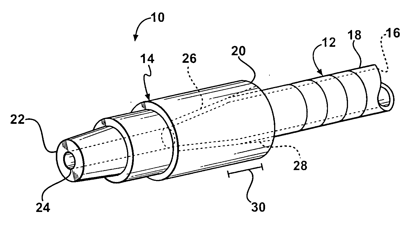
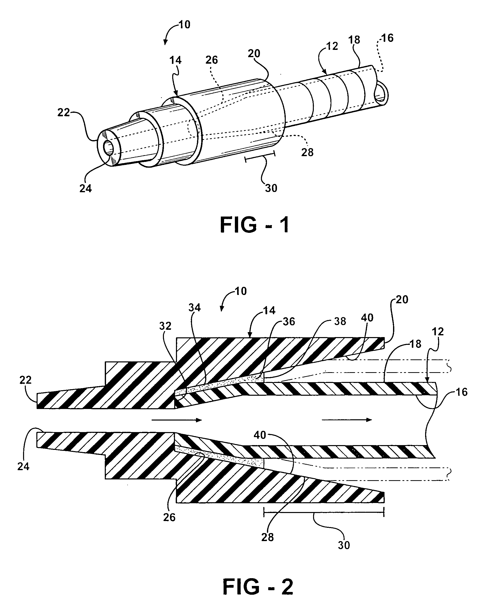
[0018] Referring now to the drawings in detail, numeral 10 generally indicates a high-pressure tubing set in accordance with the present invention. The high-pressure tubing set is capable of withstanding fluid pressures of up to 500 psi for applications such as contrast media injection by power fluid movers, injectors or similar, while at the same time is of suitable flexibility to be used as a low-pressure IV extension set. In the present high-pressure tubing set, the strength of the high-pressure set is achieved by moving the generally solvent-weakened attachment point / area of tubing to a fitting completely inside of, and underneath, the shelter of the fitting itself and / or the shelter of a circumferential reinforcement member.

[0019] As shown in FIGS. 1 and 2, in a first embodiment of the present invention, the high-pressure tubing set 10 includes tubing 12 having an end, such as a length of medical tubing or similar, and a fitting 14. The tubing 12 has an inner wall 16 defining ...


PUM

PropertyMeasurementUnit
pressuresaaaaaaaaaa
pressureaaaaaaaaaa
pressureaaaaaaaaaa

Abstract

A high-pressure tubing set includes a fitting and tubing having an end. The fitting has opposing ends and an aperture extending from one of the ends to the other end. The aperture has a tapered portion extending inwardly from one of the ends. The tubing end is received in the tapered portion and is chemically bonded thereto on an inner surface of the tapered portion, and defines a bonded portion, at a distance spaced from an end of the fitting, the end defining a beginning of the tapered portion. Fluid pressure within the tubing urges the tubing between the beginning of the tapered portion and the bonded portion outwardly, increasing the strength of the connection between the fitting and the tubing.

Description

TECHNICAL FIELD [0001] This invention relates to medical infusion sets, and more particularly to high-pressure medical tubing sets suitable for use with contrast media injection using power injectors. BACKGROUND OF THE INVENTION [0002] It is known in the medical field, such as in the field of radiology, to use high-pressure withstanding tubing sets to safely power-inject contrast media into patients' vascular structure via peripheral IV (PIV) catheters and infusion sets. The contrast media allows for the illumination of arteries and veins during X-rays, CAT scans, and the like. Medical device manufacturers commonly produce these tubing sets by solvent bonding extruded tubing, such as tubing made from polyvinylchloride or other resins, to injection molded end fittings. Such tubing sets are capable of accommodating the lower end portion (i.e., 100 to 300 psi) of the total power-injection pressure range of 100 to 1,400 psi. [0003] However, due to the pooling of solvents at the junction...

Claims


Application Information

Patent Timeline
Patent Type & Authority Applications(United States)
IPC IPC(8): A61M39/10F16L35/00C09J5/00
CPCA61M5/007A61M39/10A61M39/12F16L33/34
Inventor PROPP, DONALDPLUTA, SHANE
Owner TRI STATE HOSPITAL SUPPLY
Why Eureka
Try Eureka