Ultrasonic transducer for liquid metal

a transducer and ultrasonic technology, applied in the field of ultrasonic transducers, can solve the problems of difficulty in efficiently making ultrasonic waves enter liquid heavy metals such as lead or lead-bismuth, which has not yet become commercially practicable, and achieves the effect of improving the accuracy of measurement, facilitating discrimination between external disturbances and received signals, and improving the sound pressure transmission efficiency of wetted interfaces

Inactive Publication Date: 2006-11-23
JAPAN ATOMIC ENERGY AGENCY INDEPENDANT ADMINISTRATIVE CORP
View PDF11 Cites 13 Cited by
  • Summary
  • Abstract
  • Description
  • Claims
  • Application Information

AI Technical Summary

Benefits of technology

[0010] In the ultrasonic transducer of the present invention, at least a front end wetted portion coming into contact with the liquid heavy metal of the oscillation transmission section is made of any of ferritic stainless steel, aluminum alloy steel having an aluminum content of 70% or more and copper alloy steel having a copper content of 50% or more, thereby being apt to transmit ultrasonic waves in the liquid heavy metal such as lead-bismuth immediately after the wetted portion is wetted with the liquid heavy metal and making the sound pressure transmission efficiency of the wetted interface higher. Accordingly, a received signal becomes larger, discrimination between an external disturbance and the received signal is facilitated and measurement precision is improved, thereby making the ultrasonic transducer applicable to a measurement system (a flow meter, a liquid level meter, th

Problems solved by technology

In this case, there is a problem of how a measurement system using ultrasonic waves should be developed as one of technologies for measuring heat transfer fluid behavior and plant process quantity (e.g. flow rate, flow velocity, liquid level, temperature and the like), which, however, has not yet become commercially practical.
Such a prior art ultrasonic transducer as described above has difficulty in efficiently making ultrasonic w

Method used


Image

  • Ultrasonic transducer for liquid metal
  • Ultrasonic transducer for liquid metal
  • Ultrasonic transducer for liquid metal

Examples


example

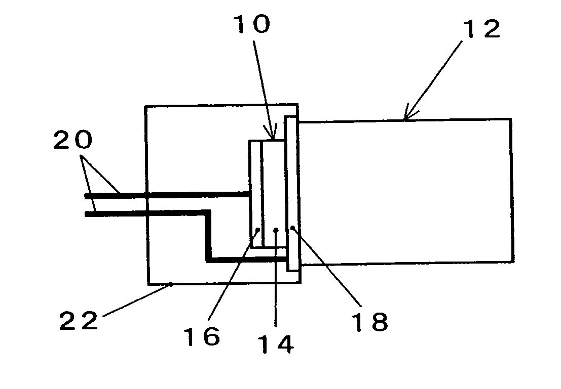
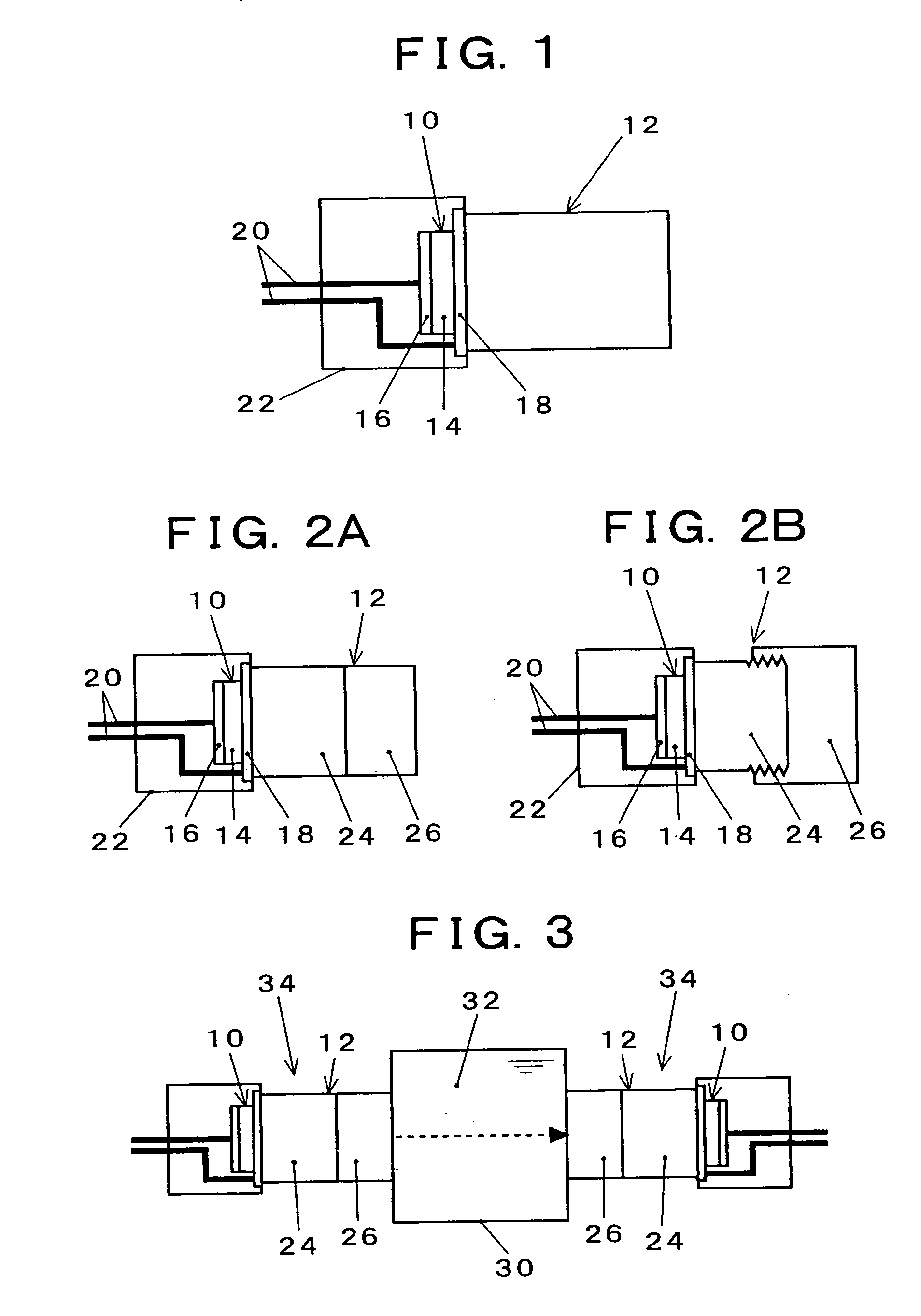
[0025]FIG. 3 illustrates an outline of a test apparatus used to confirm the effectiveness of the present invention. Liquid heavy metal (lead-bismuth) 32 is put in a container 30 and, on both ends thereof, the ultrasonic transducer 34 is attached. The ultrasonic transducer 34 comprises a combined body of the wave guide member 24 disposed in the proximity of the ultrasonic oscillator and the wetted member 26 disposed on the front end side coming into contact with the liquid heavy metal, as shown in FIG. 2A. The container 30 has a structure in which the wetted member 26 comes into direct contact with liquid heavy metal. The wave guide member 24 and the wetted member 26 are coupled to each other with a liquid acoustic coupler for high temperature (an agent to be applied to an interface between solids to improve the transmission efficiency of ultrasonic waves: water glass is used in this example). The ultrasonic transducer on one side (left-hand side in FIG. 3) is used for sending ultras...


PUM


Abstract

In an ultrasonic transducer comprising a combination of an ultrasonic oscillator 10 and an oscillation transmission section 12 and is capable of sending ultrasonic waves into liquid heavy metal through the oscillation transmission section and receiving ultrasonic waves transmitted in the liquid heavy metal, at least a front end wetted portion coming into contact with the liquid heavy metal (e.g. lead-bismuth) of the oscillation transmission section is made of any of ferritic stainless steel, aluminum alloy steel having an aluminum content of 70% or more and copper alloy steel having a copper content of 50% or more. The ultrasonic transducer improves sound pressure transmission efficiency by optimizing acoustic coupling in a wetted interface, thereby facilitating entering of ultrasonic saves into liquid heavy metal and enabling measurement of flow rate, flow velocity, temperature, liquid level, etc. with ease and high precision.

Description

BACKGROUND OF THE INVENTION [0001] The present invention relates to an ultrasonic transducer for sending and receiving ultrasonic waves into / from liquid heavy metal, and more particularly to an ultrasonic transducer for liquid metal capable of effectively sending ultrasonic waves into liquid heavy metal and effectively receiving ultrasonic waves transmitted in the liquid heavy metal by optimization of a material of a wetted portion thereof. This technology is useful for ultrasonic applied measurement of flow rate, flow velocity, liquid level, temperature, etc. of liquid heavy metal such as lead-bismuth and the like. [0002] Measurement technology of flow rate, flow velocity, liquid level, temperature, etc. using ultrasonic waves is conventionally known. For example, Japanese Patent Laid-Open No. 4-309817 discloses an ultrasonic flow meter using an ultrasonic transducer which has a structure comprises a combination of an oscillator and a metallic diaphragm. In this prior art, it has b...

Claims


Application Information

Patent Timeline
IPC IPC(8): B01J19/10
CPCG01F1/662G01N2291/02836G01F23/2968G01F15/006
Inventor HIRABAYASHI, MASARUARA, KUNIAKI
Owner JAPAN ATOMIC ENERGY AGENCY INDEPENDANT ADMINISTRATIVE CORP
Why Eureka
Try Eureka