Temperature compensated oscillator including MEMS resonator for frequency control

Active Publication Date: 2006-11-23
RGT UNIV OF CALIFORNIA
View PDF3 Cites 23 Cited by
  • Summary
  • Abstract
  • Description
  • Claims
  • Application Information

AI Technical Summary

Benefits of technology

[0007] To address these limitations experienced with MEMS resonators, this invention relies on redundancy of similar resonators integrated on chip in order to fulfill the requirement of one single quartz

Problems solved by technology

The main advantage relies in the form factor and path to on-chip integration, but this is at the expense of accuracy of the resonance frequency and higher temperature drift.
. . ) and makes a difficult trimming of the frequency nec

Method used


Image

  • Temperature compensated oscillator including MEMS resonator for frequency control
  • Temperature compensated oscillator including MEMS resonator for frequency control
  • Temperature compensated oscillator including MEMS resonator for frequency control

Examples


Embodiment Construction

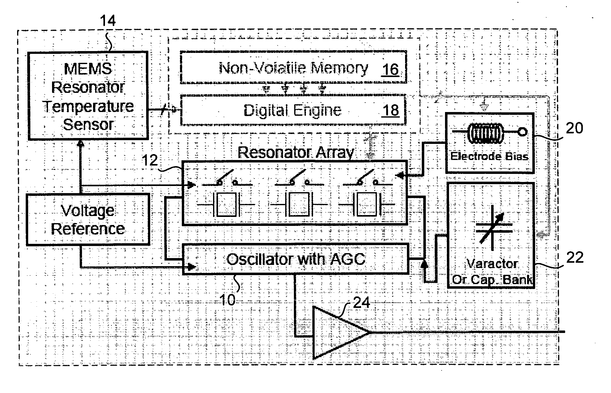
[0017] The invention provides temperature compensation for an oscillator by including an array of resonators with the oscillator, each resonator having a temperature dependent oscillator frequency. A switch selectively switches each resonator with the oscillator circuit depending on temperature.

[0018] Using the ability to stack resonators (Silicon Germanium for example) directly on top of CMOS chips, it is possible to link an array of similar resonators to a unique oscillator, and switch from one resonator to the other when the frequency of the resonator in use is out of range because of temperature drift. A high level architecture of a temperature compensated oscillator based on this concept is depicted on the diagram in FIG. 1. Here an oscillator with automatic gain control 10 has a frequency determined by resonator array 12. Temperature sensor 14 establishes resonator selection and a digital engine 16 and memory 18 set electrode bias at 20 and varactor capacitance 22. Oscillator...


PUM


Abstract

Disclosed is an oscillator that relies on redundancy of similar resonators integrated on chip in order to fulfill the requirement of one single quartz resonator. The immediate benefit of that approach compared to quartz technology is the monolithic integration of the reference signal function, implying smaller devices as well as cost and power savings.

Description

CROSS REFERENCE TO RELATED APPLICATIONS [0001] This application claims priority under 35 U.S.C. §119 to U.S. Provisional Patent Application no. 60 / 660,211, filed on Mar. 9, 2005, which is incorporated by reference herein for all purposes.STATEMENT OF GOVERNMENT RIGHTS [0002] The U.S. government has rights in the disclosed invention pursuant to grants to The University of California including DARPA No. N66001-01-1-8967.BACKGROUND OF THE INVENTION [0003] The invention relates generally to frequency oscillators, and more particularly the invention relates to the use of temperature dependent resonators to establish oscillation frequency. [0004] It has been shown that RF surface micro-machined MEMS resonators were potential replacement part for quartz resonators in reference oscillator applications. The main advantage relies in the form factor and path to on-chip integration, but this is at the expense of accuracy of the resonance frequency and higher temperature drift. [0005] Indeed for...

Claims


Application Information

Patent Timeline
IPC IPC(8): H01L41/09
CPCG01K7/32H03H9/02448G04G3/04H03H2009/02496H03H9/2473
Inventor QUEVY, EMMANUEL P.HOWE, ROGER T.
Owner RGT UNIV OF CALIFORNIA
Why Eureka
Try Eureka