Signaling compression/decompression with improved efficiency

a signaling message and compression technology, applied in the field of signaling message compression/decompression with improved efficiency, can solve the problems of large message size, transmission delay, and message size optimization, and achieve the effect of simple signaling compression, simplified compression implementation, and improved signaling compression

Active Publication Date: 2006-11-23
INTELLECTUAL VENTURES I LLC
View PDF7 Cites 26 Cited by
  • Summary
  • Abstract
  • Description
  • Claims
  • Application Information

AI Technical Summary

Benefits of technology

[0029] Thereby, a better compression of the first or first few messages can be achieved. Moreover, compression implementation can be simplified, since there is no need to “switch” after learning of the compression parameter information, e.g. version or capacity, of the other endpoint.
[0030] As additional advantages, a quite simple signaling compression is provided which can be used on one direction only, and which can interoperate with existing specifications, e.g. RFC 3486.
[0031] Furthermore, an advertised capability information can be extended so that possibly already known bytecodes can be advertised, which leads to an improved compression ratio during negotiation phase and enables selection of a compression algorithm also for uplink direction. Moreover, this provides an opportunity to decode decompression algorithms more efficiently, as it is possible to decompress without using the virtual machine and without bytecode. Consequently, it is still possible to introduce new more developed (external) compression algorithms. If the new advertise parameter is added, the information about bytecode storage can be received also in cases of one-directional compressions.
[0041] Furthermore, the at least one bytecode can be modified or replaced in a response message transmitted in response to the protocol message, if the at least one bytecode is not supported. Then, the modified or replaced bytecode is transmitted under a different parameter name. Optionally, the at least one bytecode can be stored at a reception end. As an example, the at last one bytecode can be stored in a Subscriber Identity Module (SIM) of a terminal device. The storing can be performed based on a priority allocated to the at least one bytecode, so that deletion of old bytecodes can be better controlled.

Problems solved by technology

As a result, their messages have not been optimized in terms of size.
With the planned usage of these protocols in wireless handsets as part of cellular networks, the large message size is problematic.
With low-rate IP (Internet Protocol) connectivity the transmission delays are significant.
Taking into account retransmissions and the multiplicity of messages that are required in some flows, at least call setup and feature invocation are adversely affected.
Without SigComp, the transmission latency will lead to long call setup time that would not be acceptable to end users.
First, SigComp is not fast enough.
But that means the first message cannot be compressed in an optimal way.
To make the problem even worse, there may be cases where the transmitter has to send more than one message before there is a message on the reverse direction.
It means multiple messages—not just the first one—cannot be compressed optimally.
Second, implementation of SigComp is complicated.
Such a “switch” would add significant complexity to the implementation.
Third, SigComp does not work for asymmetric situation, where SigComp is applied on one signaling direction only.
However, the size of the bytecode is several hundreds of bytes, so transmitting the bytecode via air interface leads to a reduced compression ratio.
In addition, the network has no way to effect what algorithm a terminal device uses in compression.
It might use a very slow or inefficient algorithm.
Or, an efficient algorithm my be used, which however consumes very much processing time and thus limits the number of users the network can serve.
Thus the same bytecode is sent via air-interface several times an hour, which is reducing the overall capacity and benefit of the compression.
An additional problem on the network side is that when a bytecode is received from many terminals, the network may need to calculate a SHA-1 value to get a state-id for the same bytecodes all the time.
This generates unnecessary processing load in the network server and may actually limit the number of users it can serve.

Method used


Image

  • Signaling compression/decompression with improved efficiency
  • Signaling compression/decompression with improved efficiency
  • Signaling compression/decompression with improved efficiency

Examples


Embodiment Construction

[0048] In the following, the preferred embodiments of the present invention will be described in connection with a SigComp signaling compression scheme as defined in RFC 3320.

[0049] In section 3.3. of RFC 3320, five SigComp parameters are described. They affect how a SigComp receiver processes a received SigComp message. In order to have successful SigComp operations, a SigComp transmitter needs to know the values of these parameters of the receiver. The five SigComp parameters are used to define a decompression memory size (decompression_memory_size), a state memory size (state_memory_size), the number of cycles per bit (cycles _per-bit), a compression version (SigComp_version), and a locally available state (a set containing 0 or more state items), respectively.

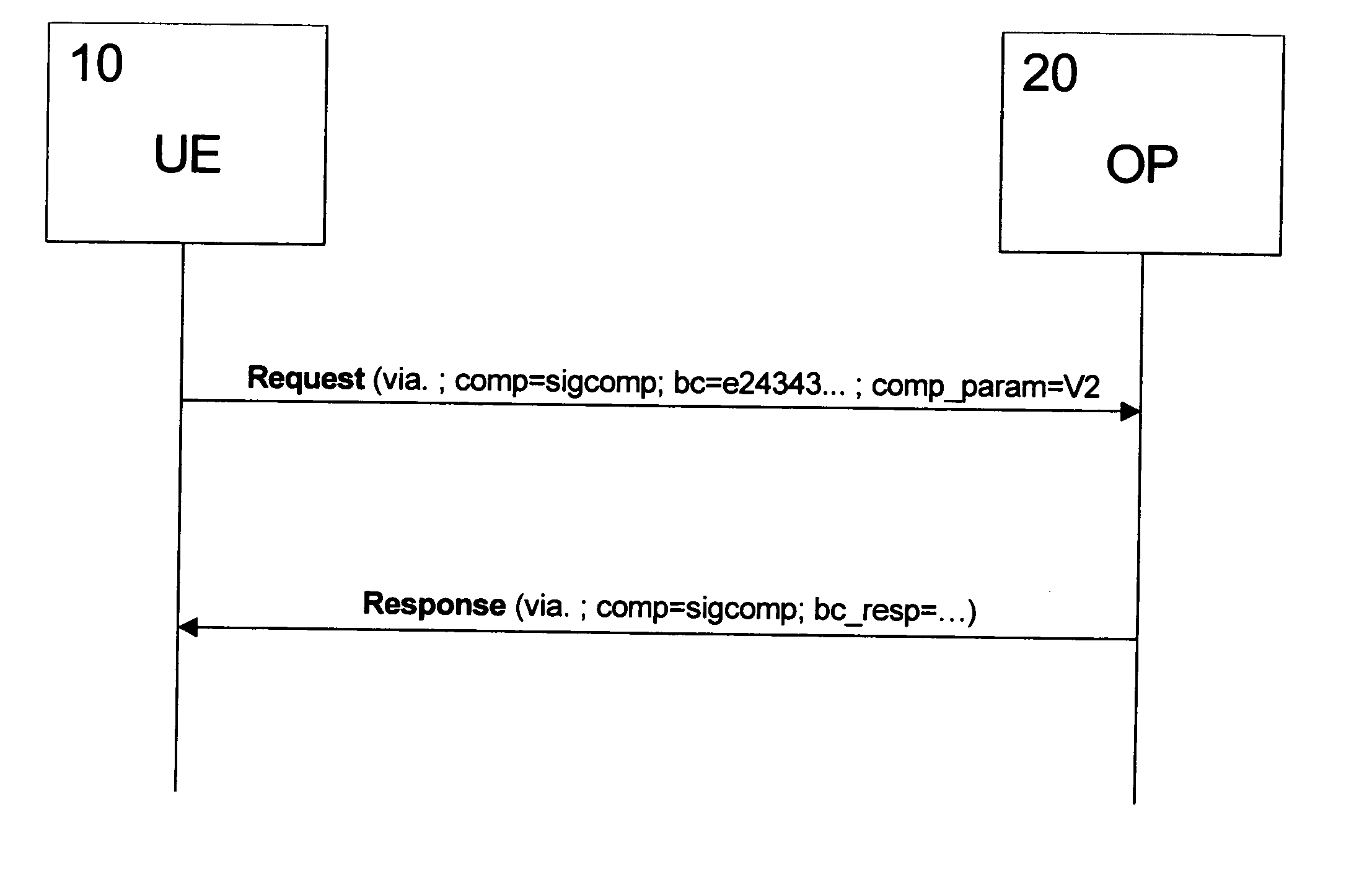
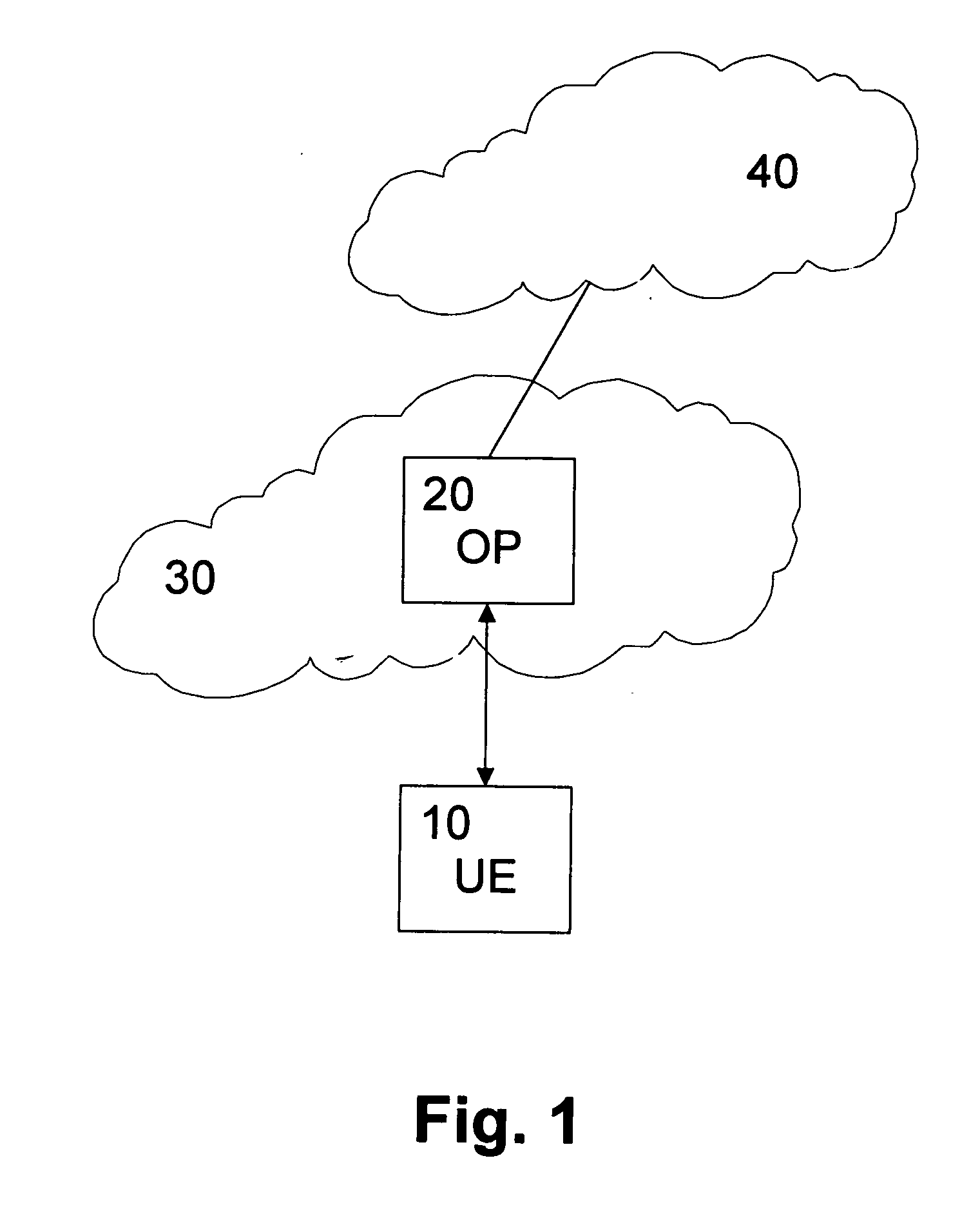
[0050]FIG. 1 shows a schematic diagram of a network environment according to the preferred embodiment. The SIP user agent (not shown) provided in a user equipment (UE) 10 or other terminal device exchanges SIP messages vi...


PUM


Abstract

The present invention relates to a method of compressing or decompressing a signaling message in a packet data network, wherein a parameter information is provided in a header portion of a protocol message of the packet data network. The parameter information specifies at least one processing detail of a compression or decompression mechanism and is forwarded together with the protocol message through the packet data network to a compression or decompression function of the packet data network. The compression or decompression mechanism at the compression or decompression function is then set in accordance with the parameter information. Thereby, a better compression of the first or first few messages can be achieved, as the parameter information is directly available.

Description

FIELD OF THE INVENTION [0001] The present invention relates to a method and apparatus for compressing or decompressing a signaling message in a packet data network. BACKGROUND OF THE INVENTION [0002] Many application protocols, like SIP (Session Initiation Protocol) or RTSP (Real-Time Streaming Protocol), used for multimedia communications are text-based and engineered for links having wide bandwidth. As a result, their messages have not been optimized in terms of size. For example, typical SIP messages range from a few hundred bytes up to two thousand bytes or more. SIP is defined by the IETF (Internet Engineering Task Force) in RFC (Request for Comment) 3261 and is an application-layer protocol used for (among other things) establishing, handling and releasing end-to-end multimedia sessions. With the planned usage of these protocols in wireless handsets as part of cellular networks, the large message size is problematic. With low-rate IP (Internet Protocol) connectivity the transm...

Claims


Application Information

Patent Timeline
Patent Type & Authority Applications(United States)
IPC IPC(8): H04J3/18H04J3/22H04J3/16H04L12/56H04L12/28
CPCH04L29/06027H04L65/1006H04L69/04H04L65/1104H04W28/06H03M7/30H04L65/1101
Inventor LIU, ZHIGANGJUTILA, SAMIPESONEN, ILKKA
Owner INTELLECTUAL VENTURES I LLC
Why Eureka
Try Eureka