Laser beam processing machine

a laser beam and processing machine technology, applied in metal working equipment, manufacturing tools, welding/soldering/cutting articles, etc., can solve the problems of not always satisfactory for practical use, long time to form a thick layer enough to divide the wafer accurately, etc., and achieve the effect of simple structur

Active Publication Date: 2006-11-30
DISCO CORP
View PDF9 Cites 58 Cited by
  • Summary
  • Abstract
  • Description
  • Claims
  • Application Information

AI Technical Summary

Benefits of technology

[0007] It is an object of the present invention to provide a laser beam processing machine capable of forming two deteriorated layers at the same time in the thickness direction of a workpiece with a simple structure.
[0015] In the laser beam processing machine of the present invention, a laser beam oscillated from the laser beam oscillation means is separated into normal light and abnormal light by the birefringence lens, and the normal light and the abnormal light are respectively converged by the condenser lens to form the focal point of the normal light and the focal point of the abnormal light. Therefore, two deteriorated layers can be formed at the same time. With the laser beam processing machine of the present invention, which has a simple structure and comprises the birefringence lens, two deteriorated layers can be thus formed in the thickness direction of the workpiece at the same time.

Problems solved by technology

Therefore, when the thickness of the wafer is relatively large, it takes long time to form a deteriorated layer thick enough to divide the wafer accurately.
However, this laser beam processing machine comprises a relatively complicated mechanism for forming a plurality of focal points and therefore, is not always satisfactory for practical use.

Method used


Image

  • Laser beam processing machine
  • Laser beam processing machine
  • Laser beam processing machine

Examples


Embodiment Construction

[0021] Preferred embodiments of a laser beam processing machine constituted according to the present invention will be described in detail hereinunder with reference to the accompanying drawings.

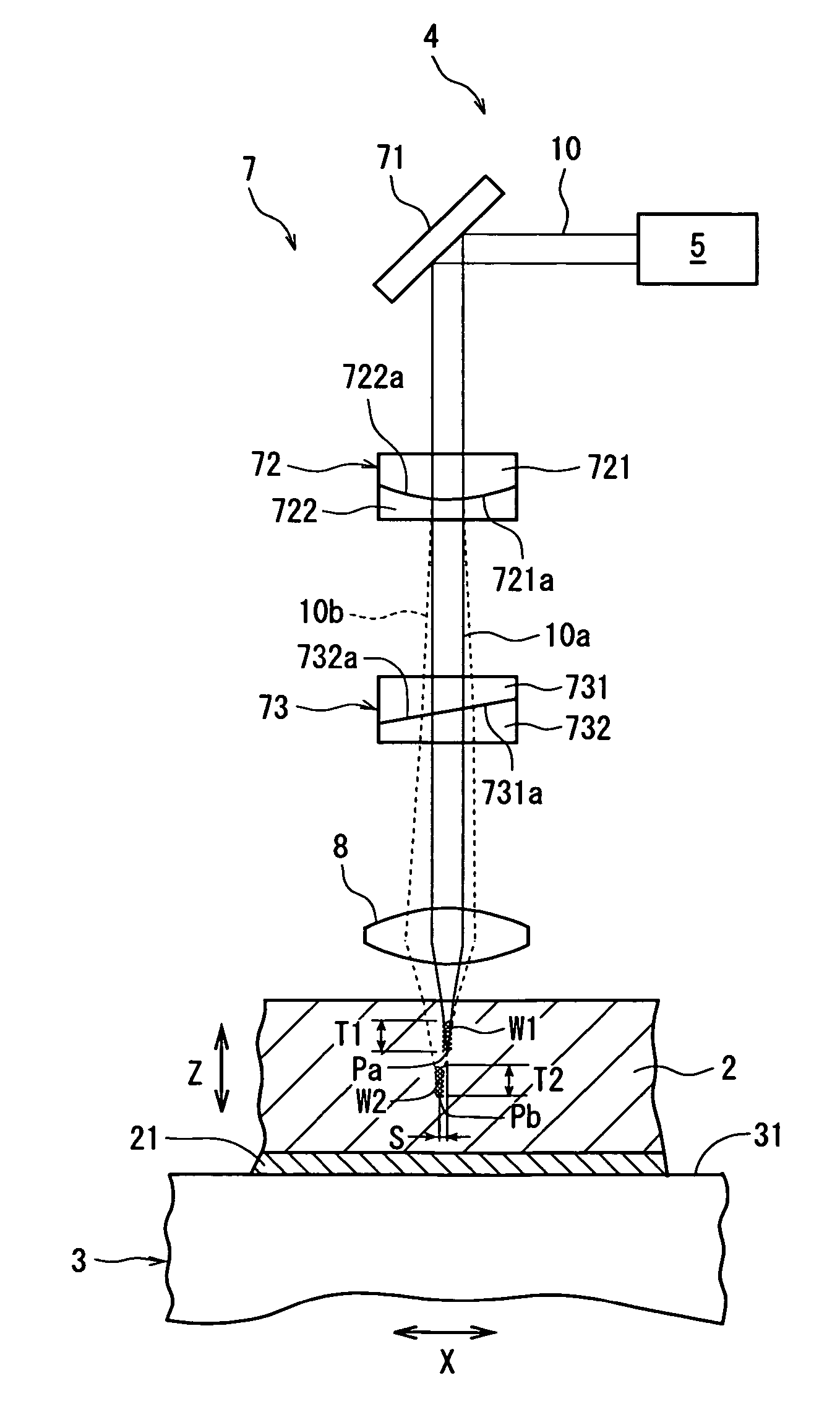
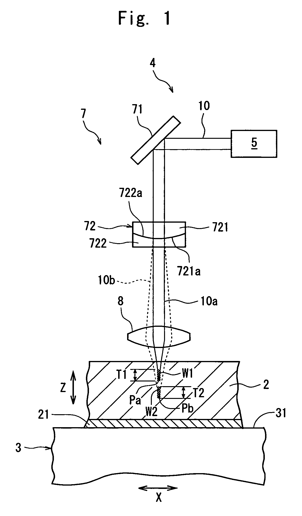
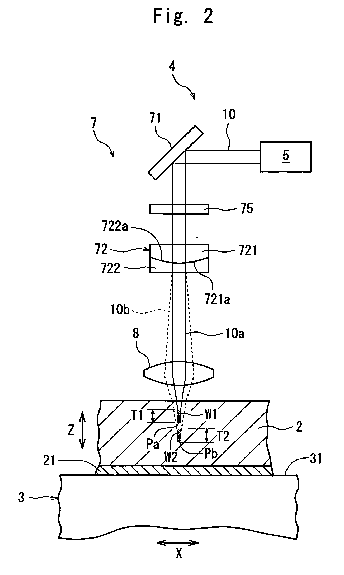
[0022]FIG. 1 is a schematic diagram of an embodiment of a laser beam processing machine constituted according to the present invention. The laser beam processing machine shown in FIG. 1 comprises a chuck table 3 for holding a wafer 2 as a workpiece and a laser beam application means denoted by 4 as a whole.

[0023] The chuck table 3 comprises an adsorption chuck 31 made of a porous member or having a plurality of suction holes or grooves, and the adsorption chuck 31 is communicated with a suction means that is not shown. Therefore, when the circuit side, onto which a protective tape 21 is affixed, of the wafer 2 as a workpiece is placed on the adsorption chuck 31 and the suction means (not shown) is activated, the wafer 2 is suction-held on the chuck table 3. The chuck table 3 constituted as...


PUM

PropertyMeasurementUnit
thicknessaaaaaaaaaa
wavelengthaaaaaaaaaa
curvature radiusaaaaaaaaaa

Abstract

A laser beam processing machine comprising a chuck table for holding a workpiece, a laser beam application means for applying a laser beam capable of passing through the workpiece to the workpiece held on the chuck table, and a processing-feed means for moving the chuck table and the laser beam application means relative to each other, the laser beam application means comprising a laser beam oscillation means, an optical transmission means for transmitting a laser beam oscillated from the laser beam oscillation means and a condenser lens for converging a laser beam transmitted by the optical transmission means, wherein the optical transmission means comprises a birefringence lens for separating the laser beam oscillated from the laser beam oscillation means into normal light and abnormal light; and the condenser lens converges respectively the normal light and the abnormal light separated by the birefringence lens to form the focal point of the normal light and the focal point of the abnormal light.

Description

FIELD OF THE INVENTION [0001] The present invention relates to a laser beam processing machine for applying a laser beam such as a pulse laser beam capable of passing through a workpiece such as a semiconductor wafer to form deteriorated layers in the inside of the workpiece. DESCRIPTION OF THE PRIOR ART [0002] In the production process of a semiconductor device, a plurality of areas are sectioned by dividing lines called “streets” formed in a lattice pattern on the front surface of a wafer comprising a suitable substrate such as a silicon substrate, sapphire substrate, silicon carbide substrate, lithium tantalate substrate, glass substrate or quartz substrate, and a device (functional device) such as IC or LSI is formed in each of the sectioned areas. Individual semiconductor devices are manufactured by cutting this wafer along the dividing lines to divide it into the areas on which a functional device has been formed. As a means of dividing the wafer, various methods making use of...

Claims


Application Information

Patent Timeline
Patent Type & Authority Applications(United States)
IPC IPC(8): B23K26/06
CPCB23K26/0057B23K26/0639B23K2201/40B23K26/0665B23K26/4075B23K26/0648B23K26/40B23K26/064B23K26/53B23K2101/40B23K2103/50
Inventor NOMARU, KEIJI
Owner DISCO CORP
Why Eureka
Try Eureka