
Tire abnormal state monitoring system for an automotive vehicle

Inactive Publication Date: 2006-11-30
FORD GLOBAL TECH LLC
View PDF28 Cites 70 Cited by
  • Summary
  • Abstract
  • Description
  • Claims
  • Application Information

AI Technical Summary

Benefits of technology

[0018] One advantage of such a system is that it may be used to detect the tire pressure drops regardless of the vehicle operation condition (accelerating, decelerating and braking) and the road condition (straight, curving, rough, smooth, banked or graded). The other advantage of such a system is that it may be used to trigger control adjustment in vehicle stability control systems so as to achieve better control performance.

Problems solved by technology

More specifically, their normality has an impact on the safety, handling and fuel economy of the vehicle, for example: Low tire pressure may cause unstable vehicle motion.
Tire tread separation may lead to a variety of unstable vehicle motions.
For example, a tire separation at rear wheels could induce over-steer which makes the vehicle more unstable.
Severe tire wear may cause an untrue driving feeling and degrade vehicle handling performance.
Tire imbalance may cause tire grip variation, which in turn may cause a varying stability.
It could also impact the braking distance of a vehicle especially during high speed driving.
Mini tire usage may cause an inaccurate computation of the tire slip, which may cause a false activation of brake controls including anti-lock brakes (ABS), traction control (TCS), roll stability control (RSC) and yaw stability control (YSC).
Tread wear variation due to normal wear or if only two tires of a vehicle are replaced may make the vehicle more unstable in snow and wet surface driving.
Since the driving condition other than the above stable / straight driving condition may generate similar wheel speed differences, differentiating those differences is a challenge.
The above-mentioned methods are not able to detect tire pressure drops if the road and the vehicle operating conditions are not favorable enough to excite the involved vibrations.
For example, if a tire leaks when driven on a curving road at a high speed, and at the same time the vehicle is braking, the aforementioned algorithms cannot detect the leak until the vehicle reaches the road conditions which allow the system to work.

Method used


Image

  • Tire abnormal state monitoring system for an automotive vehicle
  • Tire abnormal state monitoring system for an automotive vehicle
  • Tire abnormal state monitoring system for an automotive vehicle

Examples


Embodiment Construction

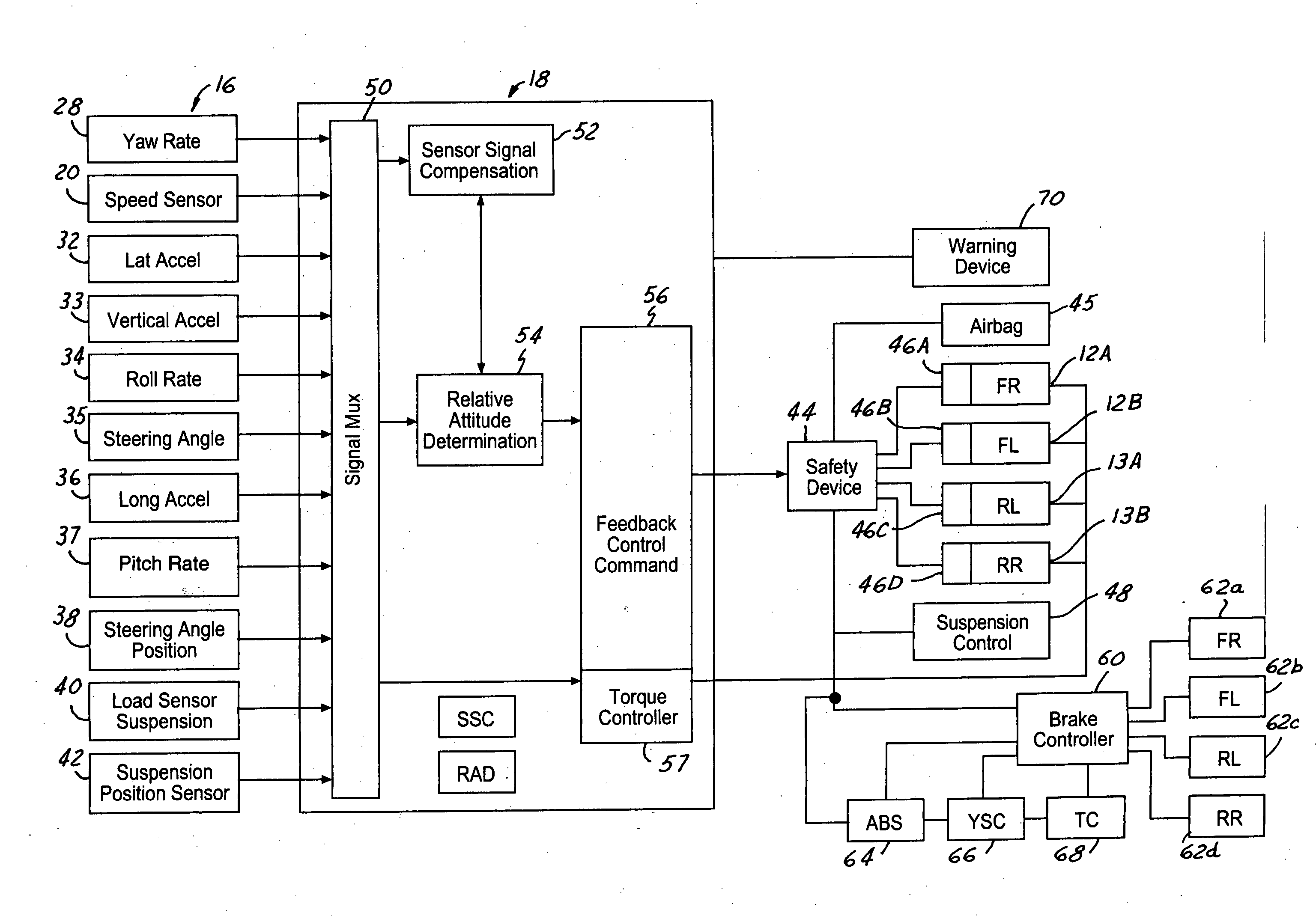
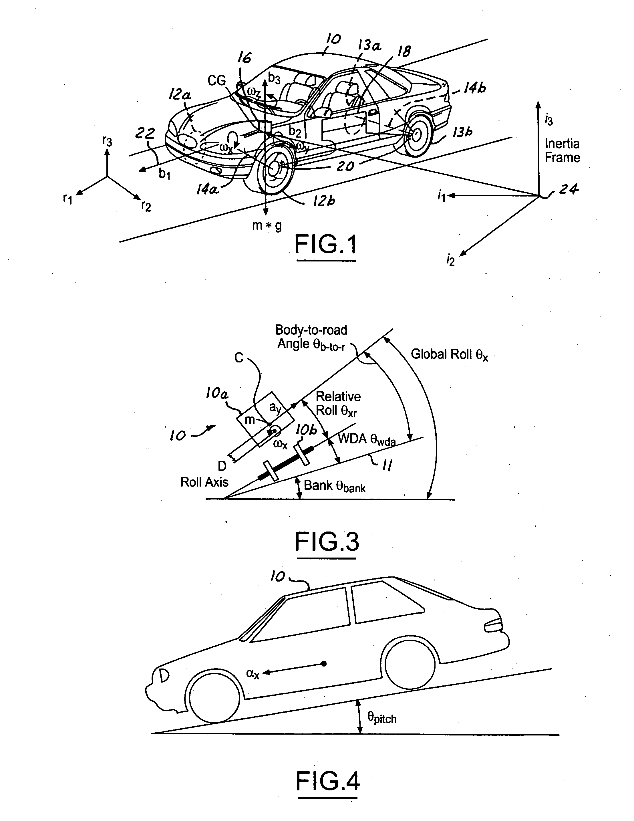
[0037] In the following figures, the same reference numerals will be used to identify the same components. The present invention may be used in conjunction with a dynamic control system such as a rollover control system for a vehicle. However, the system may be used as a driver warning device. The present invention will be discussed below in terms of preferred embodiments relating to an automotive vehicle moving in a three-dimensional road terrain. Also, the system may be used with a four-wheel drive or all-wheel drive vehicle. Such a vehicle is generally referred to as a four driven wheel vehicle since each of the wheels is capable of generating longitudinal forces derived from the powertrain.

[0038] Referring to FIG. 1, an automotive vehicle 10 with a safety system of the present invention is illustrated with the various forces and moments thereon. Vehicle 10 has front right (FR) and front left (FL) wheel / tires 12a and 12b and rear right (RR) wheel / tires 13a and rear left (RL) whe...


PUM


Abstract

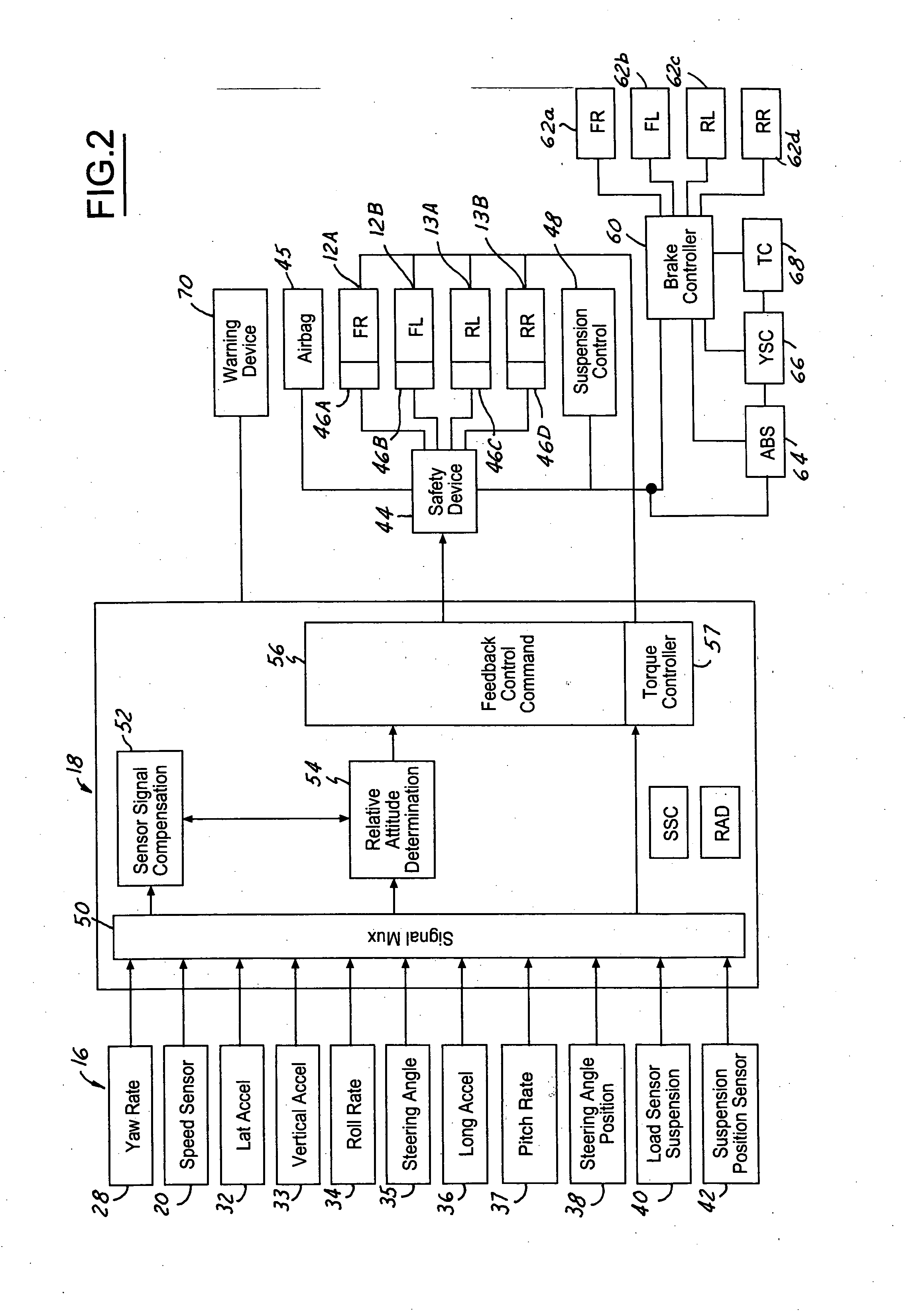
A control system for controlling an automotive vehicle (10) is set forth. Various tire parameters such as a rolling radius, a vertical spring rate, and a tire rotational spring rate may be used to determine a tire abnormal state. The vehicle (10) is controlled in response to the tire abnormal state. To control the vehicle various dynamic control systems such as anti-lock brakes, traction control, various sensors existing in the vehicle such as a yaw signal, roll signal and pitch signal may be used to determine a tire parameter.

Description

TECHNICAL FIELD [0001] The present invention relates generally to a tire monitor for an automotive vehicle and, more specifically, to a system that monitors an abnormal state of a tire of a moving vehicle including but not limited to a significant tire pressure drop, tire imbalance, the presence of a mini tire, severe tire wear and tire tread separation. BACKGROUND [0002] Since the tire / road contact patches determine the dynamic behavior of an automobile, tires are an important safety-critical part of an automobile. More specifically, their normality has an impact on the safety, handling and fuel economy of the vehicle, for example: [0003] Low tire pressure may cause unstable vehicle motion. [0004] Tire tread separation may lead to a variety of unstable vehicle motions. For example, a tire separation at rear wheels could induce over-steer which makes the vehicle more unstable. Some of the contributions of the tire separation include low tire pressure and high operating temperature. ...

Claims


Application Information

Patent Timeline
IPC IPC(8): B60Q1/00
CPCB60C23/061B60C23/062B60T2240/08B60T2240/06B60T2240/07B60G2800/984B60C11/246
Inventor LU, JIANBOMEYERS, JOSEPH
Owner FORD GLOBAL TECH LLC
Learn More